Thermal Imaging Lenses: Material and Coating Guide
A focused engineering guide for selecting infrared lenses in thermal imaging systems by MWIR/LWIR band, material, coating, thermal drift, lens geometry and RFQ data.
Thermal Imaging Lenses Need More Than Material Transmission
In thermal imaging systems, the infrared lens does more than pass radiation to the detector. It forms the image, controls field of view, affects measurement repeatability and determines how stable the system remains across temperature, vibration and production variation.
Many camera problems appear as haze, focus drift, low contrast, uneven image quality or temperature-measurement variation. The cause is often not only the detector or software. It can come from early decisions about lens material, coating band, F-number, surface form, centering, mounting stress or thermal compensation.
This guide focuses on infrared lenses for thermal imaging systems. Windows and protective covers are referenced where they affect the optical path, but the primary search intent is lens selection for MWIR and LWIR thermal cameras.
Define the Imaging Band First
Thermal imaging lenses must be designed around the detector band. MWIR and LWIR systems use different materials, coatings and thermal design strategies. A lens specified only as an IR lens or thermal camera lens is not specific enough for engineering review.
| Band | Common range | Typical detector context | Lens selection impact |
|---|---|---|---|
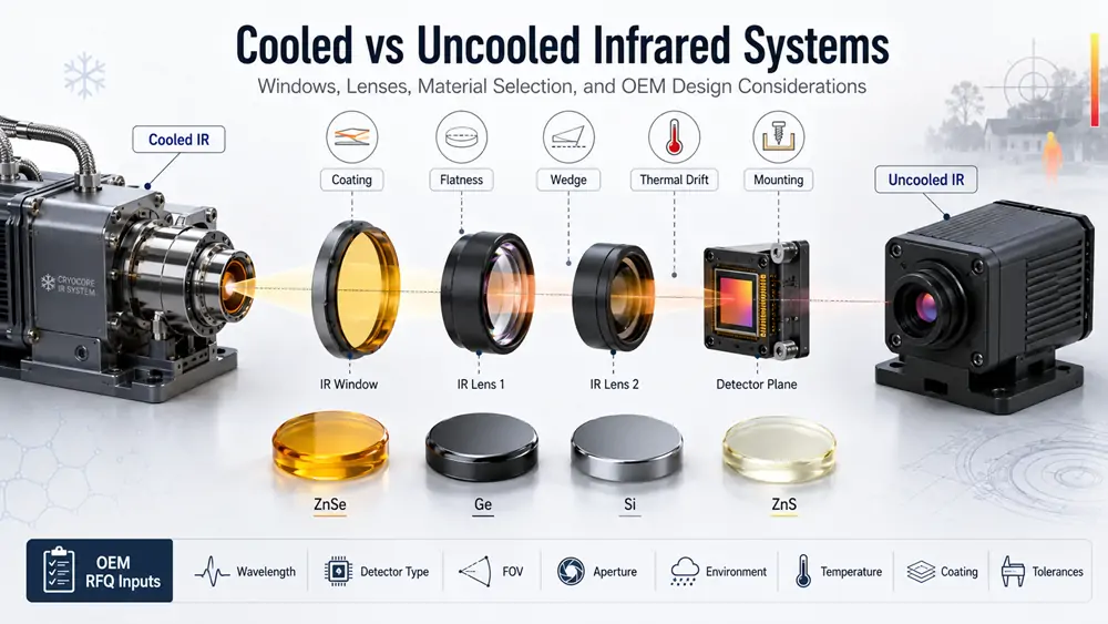
| MWIR | About 3-5 µm | Often cooled systems, high-temperature targets or long-range detection | Review silicon, germanium, ZnSe, ZnS, CaF2 or other IR materials by design target |
| LWIR | About 8-12 µm or 8-14 µm | Common in uncooled thermal cameras and room-temperature imaging | Review germanium, ZnSe, ZnS or selected specialty IR materials |
| 10.6 µm laser-related path | CO2 laser wavelength | Laser process monitoring or beam-related optical path | Review absorption, coating, contamination and laser power separately |
Exact detector response should be supplied whenever possible. For quotation and optical review, use a real wavelength range such as 3-5 µm, 8-12 µm or 8-14 µm instead of only writing MWIR or LWIR.
What Makes Lens Selection Different from Window Selection
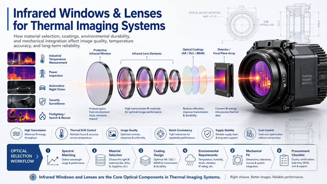
A protective window mainly protects the detector or sealed optical path while transmitting the required band. A lens must form an image. This makes lens selection more sensitive to refractive index, curvature, center thickness, surface form, centering, F-number, thermal drift and coating loss.
| Design factor | Window priority | Lens priority |
|---|---|---|
| Optical function | Transmit and protect | Focus, image and control aberration |
| Material choice | Transmission, durability and exposure | Transmission, refractive index, thermal behavior and lens form |
| Surface requirement | Flatness, parallelism, wedge and surface quality | Radius, surface form, centering, surface quality and transmitted wavefront |
| Thermal risk | Stress, cracking and transmission shift | Focus drift, image blur, calibration change and athermal design need |
| Coating risk | Reflection, durability and cleaning | Multi-surface loss, ghosting, contrast and detector signal |
Material Starting Points for Thermal Imaging Lenses
No single IR material is best for every thermal imaging lens. Material selection should combine band, detector type, field of view, operating temperature, package size, cost target and production quantity.
| Material | Typical lens use | Main strengths | Engineering cautions |
|---|---|---|---|
| Germanium | LWIR and selected MWIR thermal imaging lenses | High refractive index supports compact lens designs | Temperature-dependent optical behavior, density and coating durability must be reviewed |
| CVD ZnSe | LWIR, broadband IR and CO2 laser-related lens paths | Broad IR transmission and common use around 10.6 µm | Relatively soft; handling, cleaning, coating and packaging require care |
| Silicon | SWIR and selected MWIR lens elements | Good mechanical strength, lower density than germanium and practical manufacturability | Not a normal 8-14 µm LWIR transmission material |
| ZnS / Cleartran ZnS | Rugged MWIR/LWIR lenses, front elements or multispectral assemblies | Useful when durability, exposed position or multispectral behavior matters | Grade, scatter, transmission and polishing requirements must be specified clearly |
Germanium Lenses for LWIR Thermal Cameras
Germanium is widely used in LWIR thermal imaging lenses because its high refractive index can support compact optical systems. It is common in security cameras, industrial inspection systems, handheld thermal imagers and machine-vision thermal platforms.
The main caution is thermal behavior. As operating temperature changes, focus and image quality may shift unless the lens is designed with compensation or the working range is controlled. For outdoor or wide-temperature systems, engineers should review athermal design, mount material, temperature range and calibration strategy.
ZnSe Lenses for Selected IR and Laser-Related Systems
ZnSe can be reviewed for selected LWIR and broadband infrared lens requirements, and it is commonly used in CO2 laser optics. In a thermal imaging context, ZnSe may be relevant when wavelength range, laser compatibility, transmission behavior or custom geometry makes it a practical candidate.
Because ZnSe is relatively soft, it should not be specified without handling and coating requirements. Cleaning method, packaging, surface protection, coating side and operating exposure should be defined before release.
Silicon Lenses for SWIR and Selected MWIR Designs
Silicon can be attractive in selected MWIR or shorter-wavelength IR systems because it offers good mechanical properties and practical manufacturability. It can be useful where weight, strength and cost are important and the wavelength band is compatible.
Silicon should not be selected for normal LWIR thermal imaging around 8-14 µm. This is one of the most common material-selection errors. If the detector is LWIR, engineers should review germanium, ZnSe, ZnS or other LWIR-compatible materials instead.
ZnS and Cleartran ZnS for Rugged Thermal Imaging Optics
ZnS and Cleartran ZnS may be reviewed when the optical element faces outdoor exposure, shock, vibration, cleaning, salt fog or multispectral requirements. In some systems, the front element must provide both imaging performance and environmental durability.
For ZnS-based lens or front-element designs, grade and scatter requirements matter. The RFQ should clearly state whether standard ZnS or Cleartran ZnS is expected, and whether visible-to-IR behavior, haze, transmission or image quality is a critical requirement.
Coating Strategy for Thermal Imaging Lenses
Thermal imaging lenses often contain multiple optical surfaces. Even small reflection losses on each surface can reduce detector signal, image contrast and calibration stability. Coating should therefore be reviewed as part of the lens design, not as an afterthought.
- MWIR AR coating: Specify the detector band, angle of incidence and substrate, typically around a defined 3-5 µm range.
- LWIR AR coating: Specify the exact 8-12 µm or 8-14 µm requirement instead of using a generic LWIR label.
- Protective coating: Consider cleaning, humidity, dust, oil and abrasion when the lens surface is exposed.
- DLC coating: Often reviewed for selected germanium windows or exposed elements, but it should not be assumed suitable for every lens design.
- Laser-related coating: If CO2 laser energy is involved, review absorption, power density, beam size and contamination risk separately.
Lens Geometry and Mechanical Data to Confirm
Lens performance depends on geometry and mounting as much as material. A useful lens RFQ should provide enough data to review optical feasibility, manufacturing route and inspection scope.
| Data item | Why it matters |
|---|---|
| Focal length and F-number | Define field of view, spot/image scale and optical speed |
| Detector size and pixel pitch | Help determine image quality target and useful resolution |
| Diameter, center thickness and edge thickness | Affect material availability, strength, absorption and mounting |
| Radius, lens form and surface form | Control focusing behavior and aberration correction |
| Centering and alignment reference | Support repeatable assembly and image consistency |
| Surface quality and coating zone | Affect scatter, ghosting, contrast and inspection criteria |
| Mounting method | Controls stress, focus shift, sealing and production repeatability |
Common Lens Specification Mistakes
| Mistake | Why it creates risk | Better approach |
|---|---|---|
| Specifying only thermal imaging lens | The supplier cannot know band, FOV, detector size or material route | Provide band, detector data, focal length and application environment |
| Choosing only by material name | Material alone does not define image quality or manufacturability | Review material, geometry, coating and tolerance together |
| Ignoring thermal drift | Focus shift can degrade image and measurement repeatability | Share operating temperature range and athermal requirements |
| Using silicon for LWIR lens transmission | Silicon does not fit normal 8-14 µm LWIR transmission | Review germanium, ZnSe, ZnS or other LWIR lens materials |
| Under-specifying coating | Generic AR coating does not define final band performance | Specify substrate, wavelength range, angle and environment |
RFQ Checklist for Thermal Imaging Lenses
For faster review and fewer quotation revisions, prepare the following information before requesting a lens quote.
- Detector and band: Cooled or uncooled detector, MWIR or LWIR band, exact response range if available.
- Optical function: Front lens, objective lens, relay lens, replacement lens element or custom lens assembly.
- Image requirement: Field of view, focal length, F-number, target distance, detector size and image-quality target.
- Material preference: Germanium, ZnSe, silicon, ZnS, Cleartran ZnS or open material review.
- Geometry: Diameter, center thickness, edge thickness, radius, surface form, chamfer and centering.
- Coating: MWIR/LWIR AR band, coating side, protective coating, DLC review or laser-related condition.
- Environment: Temperature range, thermal cycling, humidity, dust, oil, salt fog, vibration, shock and cleaning process.
- Commercial data: Prototype quantity, production quantity, inspection documents, packaging and target schedule.
Related Materials and Product Paths
For material comparison, review germanium material, ZnSe material, silicon material and ZnS material. For component directions, compare ZnSe lenses, germanium aspheric lenses and silicon aspheric lenses.
Practical Recommendation
The safest lens-selection flow is to define the detector band first, then confirm field of view, focal length, F-number, material route, coating target, temperature range and mounting method. For thermal imaging, lens selection should be treated as an optical-system decision, not only a purchasing line item.
OPTOStokes-IROptical supports infrared lenses, windows, protective optics and drawing-based custom components for thermal imaging and sensing systems. For material selection, drawing review, sample evaluation or quotation, use the contact form or email [email protected].