How to Choose Protective Windows for IR Detectors
A practical guide to selecting protective windows for infrared detectors and thermal imaging sensors by wavelength, material, coating, aperture, thickness and mounting method.
Protective Windows Are Optical Components, Not Simple Covers
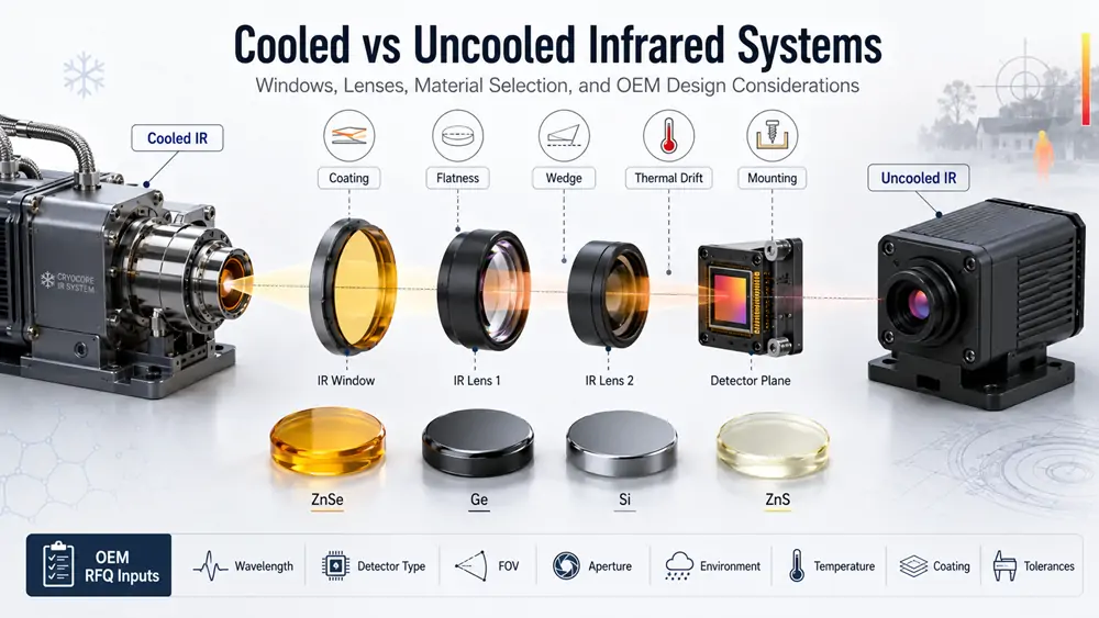
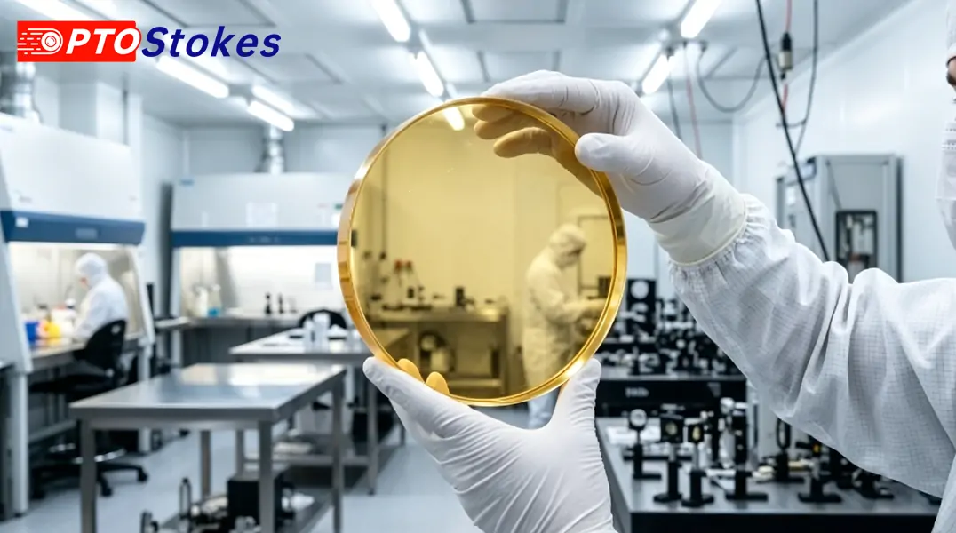
In an infrared detector, thermal imaging camera, laser monitoring module or industrial sensing system, the front protective window is often treated as a mechanical cover. That is a risky shortcut. The window is part of the optical path. Its material, coating, thickness, clear aperture, wedge, flatness and mounting stress can change signal level, image contrast, calibration stability and long-term reliability.
A good protective window must do two jobs at the same time. It must protect the detector or sensor from dust, moisture, oil, particles, cleaning contact and mechanical impact. It must also transmit the required infrared band with controlled reflection, absorption, scattering and wavefront error.
For engineering teams and OEM buyers, the correct question is not simply which infrared material has high transmission. The better question is: which window specification keeps the detector protected while preserving the usable signal in the real operating environment.
Start with the Detector Band
The operating wavelength is the first selection filter. A window material that works well in one infrared band may be unsuitable in another. Before selecting material or coating, confirm whether the system uses SWIR, MWIR, LWIR, a CO2 laser wavelength, or a custom narrow band.
| Band or use case | Typical wavelength range | Window selection focus |
|---|---|---|
| SWIR sensing | About 0.9-1.7 µm, depending on detector | Transmission, surface quality, coating match and detector package constraints |
| MWIR detection | Often 3-5 µm | Material transmission, thermal behavior, AR coating and low stray reflection |
| LWIR thermal imaging | Often 8-12 µm or 8-14 µm | Material choice, coating durability, environmental exposure and assembly stress |
| CO2 laser systems | Commonly 10.6 µm | Absorption, coating design, contamination control and thermal loading |
If the wavelength is uncertain, do not finalize the window. A protective window specified only as an infrared window can easily become the wrong part for the detector.
Core Selection Factors for IR Protective Windows
1. Transmission and optical loss
Transmission should be reviewed at the actual operating band, not as a general catalog value. Reflection loss from both surfaces, absorption inside the substrate and coating mismatch can reduce detector signal. In sensitive thermal imaging or measurement systems, small optical losses may affect image contrast or calibration repeatability.
2. Clear aperture
The clear aperture must cover the active optical path without clipping the field. Physical outside diameter and usable clear aperture are not the same. Edge bevels, retaining rings, adhesive zones and coating masks can reduce the practical aperture.
3. Thickness
Thickness affects mechanical strength, thermal mass, absorption and possible beam deviation. A thin window can reduce absorption and package size, but may be more sensitive to stress or impact. A thick window may improve robustness, but can add optical path length, absorption and weight.
4. Surface quality and flatness
Surface defects, scratches, digs, flatness error and transmitted wavefront error can matter when the window sits near a detector or inside an imaging path. For simple protection, moderate specifications may be sufficient. For precision imaging, spectroscopy or laser measurement, tighter optical specifications may be needed.
5. Parallelism, wedge and ghost control
Parallel windows can create ghost reflections in compact imaging modules. A slight wedge can move reflected energy away from the detector or image area. The decision depends on detector sensitivity, field geometry, coating performance and allowable beam deviation.
6. Mounting stress
Retaining rings, adhesive, threaded mounts and sealed packages can distort the window if the mechanical design is not controlled. Mounting stress may create wavefront error, birefringence in some optical paths, seal leakage or fracture risk. The drawing should define how the part is located, supported and loaded.
7. Environment
Outdoor thermal cameras, industrial sensors, vehicle systems and laboratory detectors face different risks. Humidity, dust, oil, salt fog, vibration, shock, high temperature, low temperature and cleaning method should all be reviewed before selecting material and coating.
Material Comparison for Protective Windows
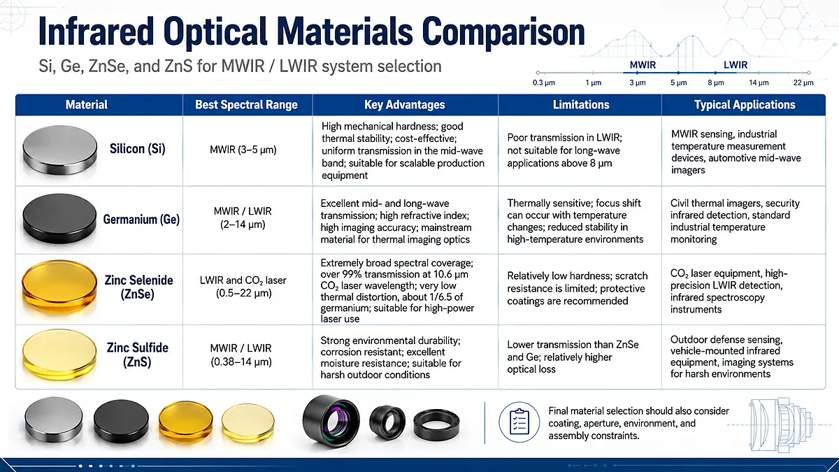
Material selection should be made from wavelength, environment, mechanical load and cost target together. The table below gives a practical starting point for common infrared window materials.
| Material | Common use | Main advantages | Engineering cautions |
|---|---|---|---|
| CVD ZnSe | LWIR windows, CO2 laser optics and broadband IR components | Broad infrared transmission and frequent use around 10.6 µm | Relatively soft; cleaning, handling, coating and packaging must be controlled |
| Germanium | LWIR thermal imaging windows and lenses | High refractive index and common use in compact thermal imaging optics | High density, higher material cost and temperature-dependent optical behavior |
| Silicon | NIR, SWIR and selected MWIR windows or substrates | Good mechanical strength, practical manufacturability and lower density than germanium | Not a normal 8-14 µm LWIR material; the working band must be confirmed |
| ZnS / Cleartran ZnS | MWIR/LWIR windows and multispectral protective covers | Useful where broader IR transmission or exposed-window durability is required | Grade, scattering, transmission range, cost and supply condition require confirmation |
For material pages and broader comparison, review ZnSe material, germanium material, silicon material and ZnS material.
Choosing Flat, Wedged and Stepped Windows
Flat windows
Flat protective windows are common where the optical path is straightforward and cost, availability and assembly simplicity matter. They are suitable for many detector covers, thermal imaging front windows and laser protection positions when ghost reflection and beam deviation are not critical.
Wedged windows
Wedged windows are used when reflected light must be displaced away from the detector, image plane or sensitive optical path. They are useful in high-sensitivity sensing, spectroscopy, laser monitoring and compact imaging modules where ghost images or interference can become visible.
Stepped windows
Stepped windows add a mechanical location feature. They can improve seating, centering and package integration when the housing requires a defined shoulder or sealing surface. The step geometry, chamfer and coating zone should be shown clearly on the drawing.
For related component paths, compare CVD ZnSe flat windows, ZnSe windows, ZnSe wedged windows and ZnSe stepped windows.
Coating Strategy
Uncoated infrared materials can have significant surface reflection. A protective window usually needs a coating strategy, but AR coating alone is not enough information for manufacturing review. The coating request should define substrate, wavelength band, angle of incidence, one-side or two-side coating, environmental exposure and cleaning requirement.
- AR coating: Reduces reflection in the target band and improves detector signal throughput.
- Broadband IR coating: Useful when the system must cover a wider detector band or multiple operating modes.
- Protective coating: Helps exposed windows tolerate cleaning, moisture, dust or handling risk.
- DLC coating: Often considered for selected germanium windows in exposed applications, but it should not be assumed suitable for every material or wavelength.
- Laser coating: Requires special attention to wavelength, beam size, power density, absorption and contamination control.
Common Selection Mistakes
| Mistake | Why it matters | Better practice |
|---|---|---|
| Selecting only by catalog transmission | It ignores coating loss, mounting stress, surface quality and operating temperature. | Review the full optical, mechanical and environmental requirement. |
| Confusing outside diameter with clear aperture | The retaining area or bevel can clip the optical path. | Define both outside size and minimum clear aperture on the drawing. |
| Using a parallel window in a ghost-sensitive path | Reflections may return toward the detector and reduce image quality. | Consider wedge, coating and angle of incidence during optical design. |
| Ignoring cleaning durability | Soft materials or weak coatings can degrade in field service. | Define cleaning method, exposure and coating durability needs. |
| Over-specifying every tolerance | Unnecessary tight tolerances increase cost and lead time without improving system performance. | Specify critical optical tolerances based on the actual detector and image requirement. |
Engineering Drawing Checklist
For a reliable quotation and manufacturing review, include the following information with the inquiry.
- Operating band: SWIR, MWIR, LWIR, CO2 laser wavelength or exact custom wavelength range.
- Material preference: ZnSe, germanium, silicon, ZnS or open material review.
- Geometry: Round, square, rectangular, flat, wedged, stepped, drilled or custom shape.
- Dimensions: Outside diameter or length and width, thickness, clear aperture and tolerances.
- Optical specifications: Surface quality, flatness, parallelism, wedge, transmitted wavefront or inspection standard if required.
- Coating: AR band, protective coating, one-side or two-side coating, angle and coating zone.
- Mechanical interface: Mounting method, sealing method, chamfer, step, retaining surface and adhesive zone.
- Environment: Temperature range, humidity, dust, oil, salt fog, vibration, shock and cleaning process.
- Commercial information: Prototype quantity, production quantity, required documents, packaging and target schedule.
Practical Recommendation
The safest selection process is to define the detector band first, then select material, coating, window geometry, thickness and mounting method as one system. For a thermal imaging sensor, the window should protect the detector without adding avoidable reflection, absorption, ghosting, stress or environmental failure risk.
If the project uses LWIR thermal imaging, CO2 laser monitoring or a custom detector package, avoid selecting by material name alone. Send the wavelength band, drawing, clear aperture, thickness, coating target, environment and quantity for review.
OPTOStokes-IROptical supplies infrared optical components for detector protection, thermal imaging, laser systems and custom OEM assemblies. For material selection, drawing review, sample evaluation or quotation, use the contact form or email [email protected].