
Diamond-like carbon on a chalcogenide lens is a thin, hard, low-friction layer deposited on a substrate that cannot be handled like glass. The coating is what lets a moulded LWIR element survive cleaning, salt air and abrasion in the field. The question buyers actually ask is narrower: which tests prove the layer will stay in place, and what do the numbers mean.
What follows is the test matrix used on DLC-coated chalcogenide optics, the physical reason behind each test, and the conditions that should be fixed on a drawing or in an RFQ before a qualification run is quoted.
Why DLC Belongs on a Chalcogenide Substrate
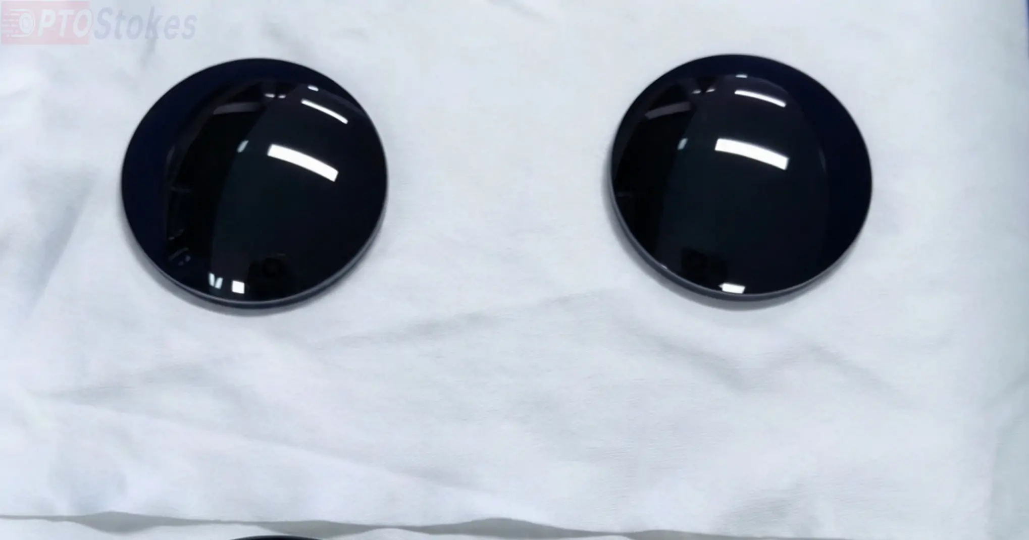
Chalcogenide glasses are chosen for MWIR and LWIR work because they can be precision moulded into aspheres and because they avoid the thermal penalty that germanium imposes on a design. Their weakness is mechanical. The surface is softer than the crystalline infrared materials and marks more easily during handling, cleaning and mounting.
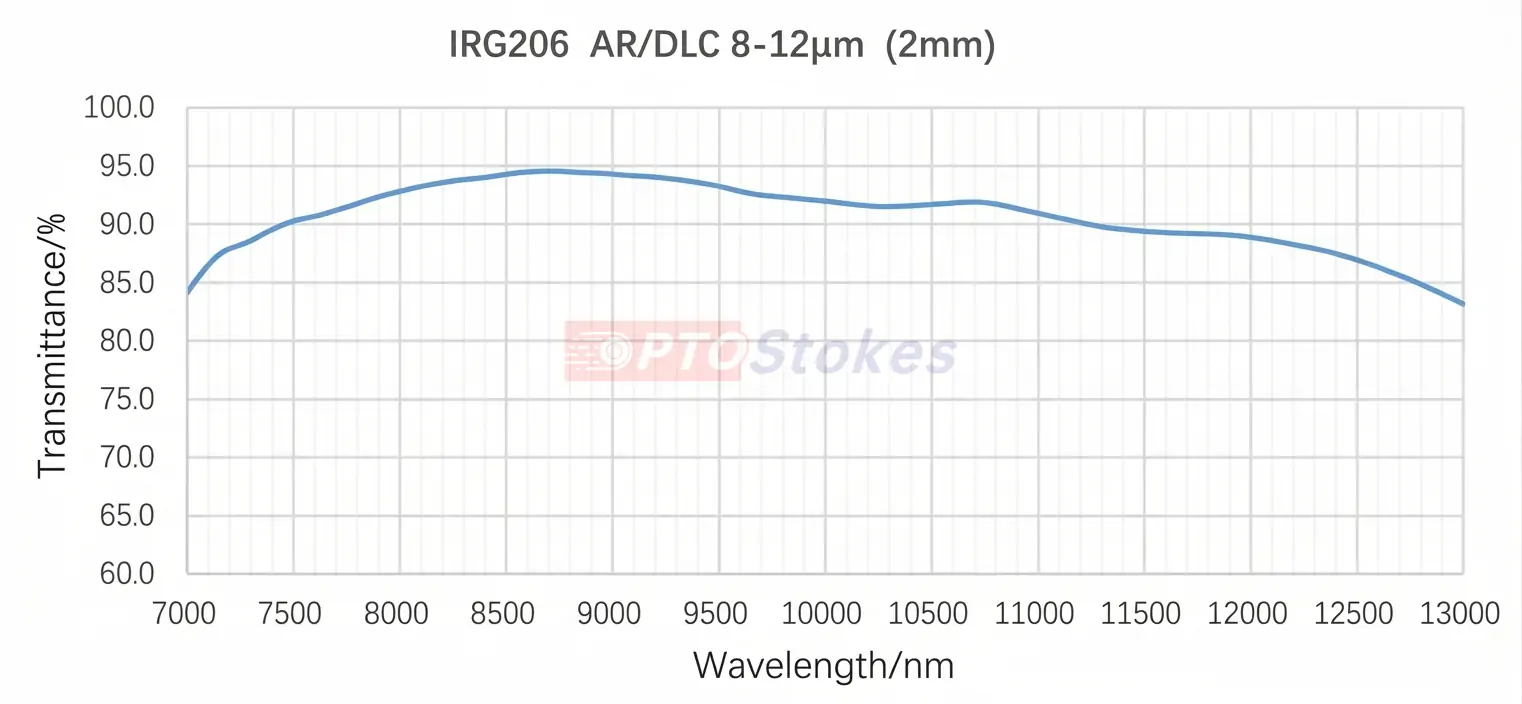
A DLC layer addresses that weakness without changing the optical design. It raises surface hardness, lowers friction, and improves resistance to corrosion and to the solvents used in cleaning. Optically it is a thin layer inside an 8–12 µm window, and coated lenses leave the process with average transmission above 92% across that band.
Chalcogenide Is Not Automatically Germanium-Free
Much of the material written about this segment calls chalcogenide optics a germanium replacement, and that shorthand causes real specification errors. Chalcogenide glass is a family, not a composition. The best-known moulding grade in LWIR use, IRG206, is a Ge-As-Se glass: it contains germanium. Arsenic-free and germanium-free variants exist, but they are different materials with different transmission, thermal and mechanical behaviour.
The accurate statement for a design review is narrower. A chalcogenide element can serve as an alternative to conventional germanium optics in selected MWIR and LWIR designs, mainly where moulded aspheres, reduced thermal defocus or lower mass matter. It is not a drop-in swap. Index, dispersion, thermo-optic behaviour and mechanical properties differ, and the design has to be re-optimised around the new material.
| Design factor | Germanium | Chalcogenide moulding glass |
|---|---|---|
| Forming route | Crystalline; ground and polished, one part at a time | Precision moulded, including aspheric and diffractive surfaces |
| Thermal defocus | Large thermo-optic coefficient; active or mechanical athermalisation usually required | Comparatively low thermo-optic coefficient; smaller focus shift, magnitude depends on the design |
| Mass | Dense; contributes significant weight in multi-element objectives | Generally lighter for the same aperture, which matters in gimbal and airborne assemblies |
| Surface durability | Hard but brittle; coating needed for environmental resistance | Softer; DLC is normally specified for handling and abrasion resistance |
| Typical role | Polished lenses and windows in established LWIR platforms | Moulded aspheres, athermal objectives, weight-sensitive and volume programmes |
DLC is deposited in vacuum, usually by plasma-enhanced chemical vapour deposition, onto the finished chalcogenide surface. The layer is thin compared with the substrate, dense and amorphous. The diamond-like label refers to the bond mix, which sets both hardness and the infrared absorption the layer adds.
That trade-off is why layer thickness is a design parameter rather than a process detail. Any increase in thickness buys wear resistance and costs transmission, so the coating has to be specified against the band the system actually uses. For wider context on how DLC compares with antireflection stacks on infrared substrates, see this review of AR and DLC coating selection for IR optics.
Two consequences follow. Transmission figures apply to the coated part, not to a material datasheet. And durability results apply to a specific stack — substrate grade, surface preparation, layer thickness — not to DLC as a category.
The Qualification Test Matrix
Six environmental tests and three mechanical tests cover the failure modes seen in service: delamination driven by thermal stress, hydrolysis at the interface, corrosion from salt air, and wear from cleaning. The conditions below are used on moulded chalcogenide elements up to 200 mm in diameter.
| Test | Conditions | Duration or cycles | Pass criterion |
|---|---|---|---|
| High-temperature storage | Unpackaged, 85 °C, then 6 h at room temperature | 168 h | No coating defect |
| Low-temperature storage | Unpackaged, −40 °C, then 6 h at room temperature | 168 h | No coating defect |
| Thermal cycling | −40 °C for 30 min and 90 °C for 30 min per cycle, ramp ≤ 5 °C/min | 120 cycles, 6 h recovery | No coating defect |
| Thermal shock | −40 °C for 30 min and 90 °C for 30 min per cycle, transfer within 3 s | 24 cycles, 6 h recovery | No coating defect |
| Damp heat | 85 °C, 85% relative humidity | 168 h | No coating defect |
| Boiling water | Deionised water at 100 °C, then air cooled to room temperature | 12 h, single exposure | No coating removal on tape pull |
| Neutral salt fog | 35 ± 2 °C, 5% NaCl, pH 6.5–7.2 | 600 h | No coating defect |
| Abrasion | 9.8 N normal load, rubber tip at 70 ± 5 IRHD | 5000 strokes | No coating defect |
| Adhesion | Cross-hatch cut, then pressure-sensitive tape pull | Single | No coating removal |
Storage tests
The two static extremes look trivial and are not. They apply a temperature the part will never see in storage, in order to load the coating and the interface through the thermal expansion mismatch between layer and substrate while no gradient exists. A stack that survives 85 °C for a week without blistering has a stable interface.
Cycling versus shock
The difference between these two tests is rate, not range. Cycling at 5 °C/min loads the interface gradually and lets the substrate follow. Shock with a 3 s transfer is close to a step change and is the harder test at identical endpoints. A stack that passes 120 cycles can still fail 24 shocks, which is why both appear in a qualification schedule rather than one serving as a substitute for the other.
Moisture: damp heat, boiling water, salt fog
Water reaches the interface through pinholes and column boundaries, and every moisture test is a different route to the same failure. Damp heat at 85/85 for 168 h is the standard humidity screen and the one most often quoted in a purchase specification. Boiling water is faster and harsher, and is better treated as a development screen than as an acceptance criterion: thermal shock on a low-conductivity chalcogenide substrate is a mechanical risk in its own right, separate from anything the coating does. Salt fog at neutral conditions for 600 h addresses marine and coastal deployment, where chloride attack on the coating edge and on the exposed substrate is the realistic threat.
Abrasion and adhesion
The 9.8 N, 5000-stroke test measures wear under a loaded rubber tip. It is not a hardness measurement, and a nanoindentation value cannot be substituted for it: one describes plastic deformation of a surface, the other describes what happens when a lens is wiped for the two-hundredth time. The cross-hatch tape pull is qualitative and detects poor surface preparation more often than it detects coating chemistry, which makes it the first test to review when adhesion fails.
Reading a Result
Three failure signatures cover most cases. A haze increase with transmission loss across the band points to interface hydrolysis. Localised blistering, or a ring-shaped lift near the edge, points to stress concentration from mounting or from clamping force applied to the coated face. Coating removal confined to the cross-hatch grid points to adhesion, and adhesion usually traces back to substrate cleaning rather than to the deposition run.
No result means anything without a stated inspection method. Visual inspection under a defined illuminance, microscope inspection at a stated magnification, and spectral re-measurement before and after each test all belong in the report. “No coating defect” is a conclusion; the method behind it is the evidence.
What to Specify Before a Qualification Run
Most disagreements about coating durability are specification disagreements that surface late. These are the items that change the result and therefore belong on the drawing or in the RFQ.
| Item | Why it changes the outcome |
|---|---|
| Substrate grade and composition | Germanium-containing and germanium-free chalcogenides differ in surface chemistry, so adhesion behaviour differs |
| Coated faces | Single-sided and double-sided coatings load the part differently and give different transmission figures |
| Clear aperture and edge condition | Edge chips and grind marks are where delamination starts |
| Layer thickness target | Sets the balance between wear resistance and transmission loss |
| Inspection method and magnification | Defines what counts as a defect and at what size |
| Sample size and sampling plan | Three parts and ten parts support different confidence statements |
| Test sequence | Adhesion after humidity is a different test from adhesion before humidity |
| Report format | Photographic records plus spectral data, traceable to the part serial number |
Where the Combination Is Used
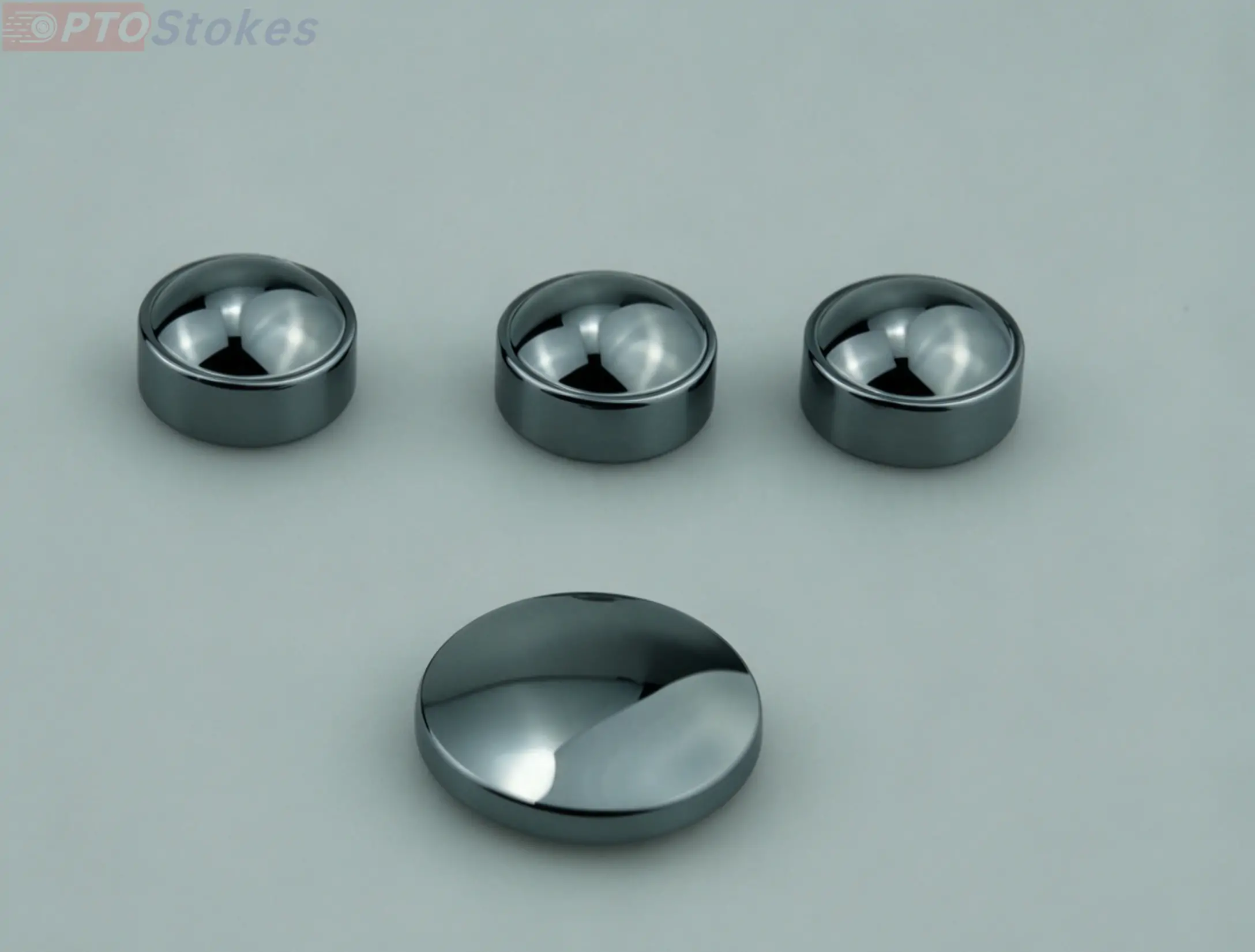
Coated chalcogenide elements appear in perimeter and border surveillance, early wildfire detection, industrial thermography, and airborne gimbal payloads — environments where the optic is cleaned often, exposed to salt or ash, and hard to service. The same properties that make moulded aspheres attractive in these systems make the coating mandatory rather than optional. A representative build is the chalcogenide glass IR window, where a moulded flat is used as a protective or sealing element in front of the detector.
For design teams comparing moulded chalcogenide against polished germanium in a new objective, the starting point is the material set rather than the coating: our chalcogenide glass optics range covers lenses, aspheres, windows and blanks, and the coating is specified after the material and the band are fixed.
Engineering Review and Quotation
If a DLC-coated chalcogenide element is entering a programme with a qualification gate, the useful first step is a specification review rather than a price. Send the drawing, wavelength range, dimensions, coating requirements including whether the DLC applies to one face or both, the operating and storage environment, and the quantity. We will confirm which tests the design actually needs, and which are being carried over from another programme's schedule without adding anything to confidence.
Drawings, spectral requirements and test schedules can be sent to sales@iroptical.com, or submitted through the contact form with the drawing attached. Coating evaluation samples can be discussed once the substrate grade and the working band are fixed.