
Most infrared designs begin with the same question: which material actually passes the band the system needs? Zinc selenide (ZnSe), germanium (Ge) and silicon (Si) cover the bulk of IR refracting optics, and supplier catalogs almost always print the three side by side. That layout is where a good number of wrong decisions begin, because the materials overlap only across part of the spectrum.
What follows is a direct comparison of transmission range, optical constants and mechanical limits, then the wavelength-based rule that decides most programs before any other specification is read.
1. Transmission Range at a Glance
| Property | ZnSe | Ge | Si |
|---|---|---|---|
| Transmission range | 0.6 – 18 µm | 2 – 14 µm | 1.2 – 7 µm |
| Refractive index (at working band) | 2.403 @ 10.6 µm | 4.003 @ 10.6 µm | 3.422 @ 4–5 µm |
| Uncoated window transmission, Fresnel loss only | ≈ 69% | ≈ 41% | ≈ 49% |
| Density | 5.27 g/cm³ | 5.33 g/cm³ | 2.33 g/cm³ |
| Knoop hardness (HK) | 120 | 780 | 1150 |
| CTE (20–300 °C) | 7.1 × 10⁻⁶/K | 6.1 × 10⁻⁶/K | 2.55 × 10⁻⁶/K |
| dn/dT (typical, 10 µm) | ≈ 61 × 10⁻⁶/K | ≈ 396 × 10⁻⁶/K | ≈ 160 × 10⁻⁶/K |
| Melting point | ≈ 1520 °C | ≈ 938 °C | ≈ 1414 °C |
| Practical upper service temperature | ≈ 250 °C in air (oxidation and plastic deformation) | ≈ 70–80 °C before free-carrier absorption degrades transmission | Several hundred °C, limited by coating and mount rather than the material |
Two notes on that table. The refractive index is quoted at a wavelength where each material is genuinely used: 10.6 µm for ZnSe and Ge, 4–5 µm for Si. A single "nd" figure taken at the helium d-line of 587.6 nm is meaningless here, because Ge and Si transmit no visible light at all. Second, melting point and practical service temperature are listed as separate rows, and for Ge they differ by more than an order of magnitude.
2. What Each Transmission Curve Looks Like
ZnSe: visible red through 18 µm
The window opens near 0.6 µm and runs to 18 µm. The 10.6 µm line sits well inside the high-transmission plateau, with bulk absorption low enough — typically below 0.0005 cm⁻¹ — that thermal lensing stays manageable in 10.6 µm optics for CO2 laser delivery.
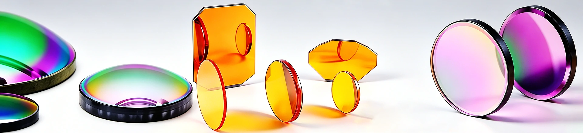
ZnSe is amber-orange in transmitted light and passes visible red. On a CO2 laser bench that is not a cosmetic detail: a HeNe or red diode beam can travel through the same ZnSe element as the 10.6 µm beam and serve as a coaxial alignment reference, so the visible spot traces the invisible path exactly. Very few IR materials allow this, and it shortens setup on every multi-element beam train.
The short-wave end is bounded by the bandgap edge near 0.5–0.6 µm, where the loss is dominated by Fresnel reflection rather than absorption. Past roughly 14 µm the curve begins to roll off toward the long-wave limit.
Ge: the 8–14 µm workhorse
Germanium starts transmitting near 2 µm and covers the middle and long-wave infrared, with 8–14 µm as its home band. It is opaque to the eye and appears dark grey.
The index is the number that shapes the hardware. At n ≈ 4.0, each uncoated surface reflects roughly 36%, so an uncoated Ge window passes only about 41% of the beam before absorption is even counted — nearly 60% lost to Fresnel reflection alone. Broadband AR coating is therefore not an upgrade on Ge, it is part of the design; the standard LWIR case is covered under 8–12 µm BBAR coatings.
Two thermal facts carry as much weight as the transmission curve. Density of 5.33 g/cm³ means a Ge window holds roughly 2.3× the mass of a Si window of identical aperture and thickness. And Ge darkens as it heats: free-carrier absorption pushes the material toward opacity above roughly 70–80 °C, while dn/dT near 400 × 10⁻⁶/K shifts focus well before that point. Uncooled LWIR cameras rarely notice either effect. High-power, hot-housing and near-furnace designs do.
Si: light, hard, and done at 7 µm
Silicon transmits from about 1.2 µm to 7 µm, covering SWIR and the MWIR band, with 3–5 µm the region most systems are designed around. Transmission falls sharply beyond 7 µm, which places both 8–14 µm and 10.6 µm out of reach — a hard cutoff, not a performance penalty.
Where Si wins is mass and durability. At 2.33 g/cm³ it is the lightest of the three, and Knoop hardness around 1150 makes it the only one of the three that tolerates an exposed, routinely wiped outer surface without special handling. Its low CTE of 2.55 × 10⁻⁶/K also keeps a window dimensionally stable across wide temperature swings. With n ≈ 3.4, an uncoated two-surface part still transmits only about 49%, so MWIR lens designs need AR coating as well — though the loss to recover is smaller than on Ge.
3. Mapping Materials to the Two Atmospheric Windows
Infrared systems are normally specified against one of two bands defined by atmospheric absorption. The band choice fixes the material list before any optical design work begins.
| Band | Wavelength | Typical targets and use | Usable materials |
|---|---|---|---|
| SWIR | 1.0 – 2.0 µm | Active illumination, laser ranging, 1.5 µm eye-safe sources, seeing through haze | Si, ZnSe |
| MWIR | 3 – 5 µm | Hot sources: engine and plume signatures, furnace and kiln monitoring, pyrometry, gas absorption near 4.2–4.3 µm | Si, Ge, ZnSe |
| LWIR | 8 – 14 µm | Ambient-temperature thermal imaging; a 300 K scene peaks near 9.7 µm, so uncooled microbolometers sit here | Ge, ZnSe |
| CO2 laser | 10.6 µm | Cutting, welding, marking, beam delivery | ZnSe |
MWIR work favours Si where weight and surface durability matter, and ZnSe where visible alignment or broadband transmission is needed. LWIR work is split between Ge, which is the default for volume uncooled cameras, and ZnSe, which brings lower absorption and the visible alignment path.
4. Where the Boundaries Actually Fall
| Band | ZnSe | Ge | Si |
|---|---|---|---|
| 0.6 – 1.2 µm (visible red to NIR) | Yes | No | No |
| 1.2 – 2.0 µm | Yes | No | Yes |
| 3 – 5 µm (MWIR) | Yes | Yes | Yes |
| 8 – 14 µm (LWIR) | Yes | Yes | No |
| 10.6 µm (CO2 laser) | Yes — first choice | Marginal, high absorption | No |
Catalog tables place the three materials in one row, and readers reasonably conclude they are interchangeable. Gate them by wavelength instead, and the list of valid options collapses to one or two entries per band. That boundary should be settled first.
Three errors account for most of the rework. Si specified into an LWIR design, where it simply stops transmitting at 7 µm. Ge specified anywhere below about 1.8 µm, which rules it out for 1.06 µm Nd:YAG and 1.5 µm SWIR paths where ZnSe or Si belong. And Ge and ZnSe assumed equivalent at 10.6 µm — both transmit at that line, but ZnSe offers the lower bulk absorption and the visible alignment route, which is why CO2 laser optics are built on it.
5. Beyond Transmission: What Actually Breaks a Design
Three second-order effects decide programs that already passed the wavelength check.
Thermal rollover. A Ge window near a hot source, or sealed in a housing with no thermal path, loses transmission as it warms instead of cracking. The symptom is gradual image dimming, and it is frequently misdiagnosed as a detector problem. ZnSe tolerates far higher temperatures but oxidises and can deform near its limit; Si is the most forgiving of the three.
Surface durability. At Knoop 120, ZnSe is soft enough that cleaning marks appear on an exposed part. Fielded systems should shield it, or specify ZnS or Si where the outer surface is exposed. ZnSe grinding dust also requires controlled handling, even though finished optics are safe in normal use.
Athermalisation. The dn/dT spread is the widest gap in this table: roughly 61 × 10⁻⁶/K for ZnSe, 396 for Ge and 160 for Si. That is why LWIR zoom lenses built on Ge require active or mechanical athermalisation while ZnSe assemblies need much less. Si's low CTE helps with mount stability but does not offset its index shift.
6. A Five-Line Selection Check
Before any material is written into a drawing, five questions settle the choice.
1. Which atmospheric band does the system look through? That alone removes one or two candidates. 2. What is the temperature at the optic, in operation and at soak? It eliminates Ge from hot-path designs. 3. What coating budget does the index allow? Ge needs aggressive BBAR, ZnSe needs less. 4. What does the mount weigh, and can it carry it? Si is 2.3× lighter than Ge at equal volume. 5. Is the outer surface exposed to handling or abrasion? That is where ZnSe loses and Si wins.
Only after those five are answered does surface figure, parallelism, centration or wedge tolerance become the deciding specification.
7. Sourcing ZnSe, Ge and Si Optics
The last variable in a material decision is rarely optical. Programs stall on availability, on whether a non-catalog size can be quoted from a drawing, and on whether anyone answers a coating question before a purchase order exists.
IROptical holds a broad in-stock catalog of ZnSe, Ge and Si windows, lenses and prisms for prototyping and volume builds, and manufactures custom parts to drawing — non-standard diameters, stepped windows, wedges, prisms and specific BBAR or DLC coating targets. Stock items ship from existing inventory. Custom work goes through drawing review before quotation, so tolerances, coating bands and inspection requirements are agreed up front rather than discovered at incoming inspection. Inspection and shipment records can be aligned to the order.
For a material recommendation against your band, a coating specification, a sample for bench testing, or a quotation on a drawing, write to sales@iroptical.com or submit the drawing through the contact form on the site. Include the wavelength range, aperture, thickness and operating temperature, and the answer can be specific instead of general.