
Introduction to F-Theta Scan Lenses
In laser scanning and material processing systems, the scan field (working area) is fundamentally determined by the focal length of the F-Theta lens. The interrelation among scan field size, focal length, working distance, and mechanical interface forms a tightly coupled system; modifying any single parameter requires a complete recalculation of the optical train.
1. Optical Path and Scan Head Integration
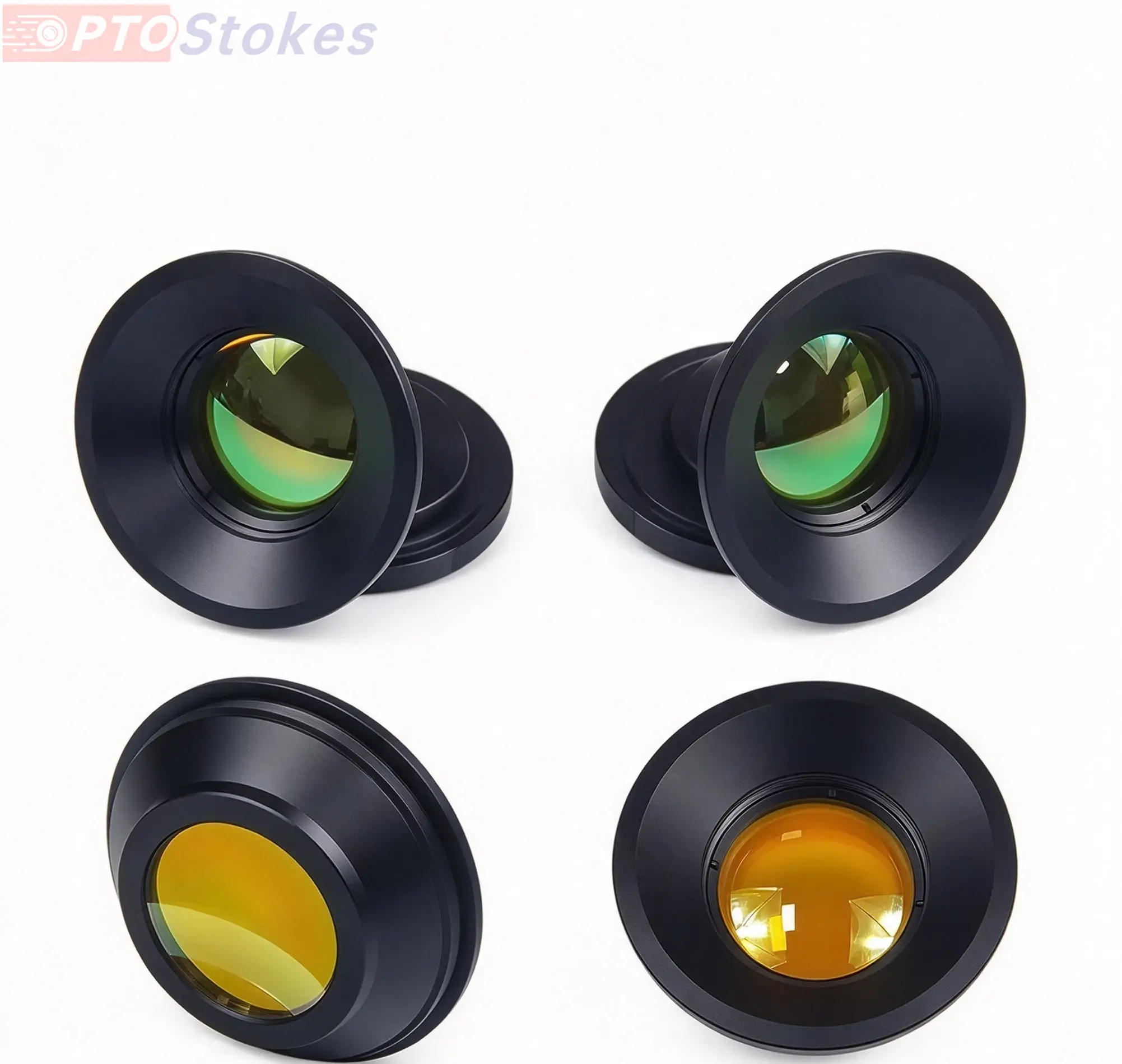
As laser beams emerge from the galvanometer scan mirrors, they no longer travel in a fixed direction. The X and Y galvo mirrors deflect the beam through a variable angle, sweeping out a conical space. The F-Theta lens is positioned between the galvanometer and the target workpiece to transform this conical scan space into a flat focal plane. Unlike conventional focusing lenses that only maintain diffraction-limited spots near a single focal point, an F-Theta lens is engineered with specialized aspheric profiles to preserve focal position and spot size across the entire flat field, maintaining a proportional relationship between scan angle and image displacement.
The entrance pupil of the F-Theta lens must precisely align with the galvanometer mirror position. A pupil misalignment causes clipping of marginal rays, resulting in premature vignetting and edge illumination drop-off. Typically integrated directly into the scan head assembly, the lens is factory-aligned for co-axial accuracy. Replacing or swapping a scan lens requires re-verification of co-axiality and back focal length. Furthermore, the numerical aperture of the lens must match the deflection angle of the galvo system; insufficient numerical aperture increases edge spot size, while an excessively large aperture unnecessarily increases lens dimensions and mass.
2. Focal Length, Scan Field, and Optical Specifications
The relationship between image height and scan angle is defined by the equation y = f · theta, where theta is expressed in radians, focal length (f) in millimeters, and image height (y) in millimeters. For this standard series, the maximum scan half-angle is designed at 0.5 radians (total scan angle of 1.0 radian), where the circular field diameter numerically equals the focal length.
| Scan Field (mm) | Circular Field Diameter (mm) | Focal Length f (mm) | Working Distance (mm) |
|---|---|---|---|
| 36 x 36 | 51 | 51 | 72 |
| 60 x 60 | 86 | 86 | 97 |
| 110 x 110 | 156 | 156 | 151 |
| 200 x 200 | 283 | 283 | 294 |
| 250 x 250 | 352 | 352 | 371 |
| 300 x 300 | 424 | 424 | 447 |
Note that the circular diameters listed in the table represent the diagonal of the scan field rather than an inscribed circle. For instance, a 36 x 36 mm square field has a diagonal of approximately 50.9 mm, rounded to 51 mm. While the stated scan field refers to square dimensions, the actual usable circular field must account for corner performance, where spot quality typically degrades compared to the axial center.
As scan fields and focal lengths scale upward, optical aperture, barrel dimensions, and total assembly weight increase proportionally. While the standardized M85x1 mechanical interface supports the entire range, lenses designed for fields of 200 x 200 mm and above require careful mass and thermal management, particularly in large-format industrial laser processing systems.
3. Working Distance and Depth of Focus
Working distance refers to the physical gap from the final optical surface of the scan lens to the focal plane, ranging from 72 mm to 447 mm across standard configurations. Working distance is distinct from focal length; for example, an f = 283 mm lens yields a working distance of 294 mm, with the differential governed by barrel mechanics, back focal length, and interface design.
Shorter working distances provide a more compact machine footprint but increase the risk of mechanical interference with clamps, assist gas nozzles, and protective windows. Conversely, longer working distances minimize physical interference but make it more challenging to suppress off-axis optical aberrations such as field curvature and relative illumination fall-off.
Working distance also directly influences depth of focus, which scales with the square of the focal length. Long-focal-length lenses provide greater depth of focus, offering higher tolerance for workpiece surface height variations, whereas short-focal-length systems demand precise focal positioning. Additionally, integration space must account for protective cover windows and coaxial gas jet nozzles positioned upstream of the workpiece.
4. Entrance Pupil and Mechanical Interfaces
Standard entrance pupil diameters are available in 11 mm and 14 mm configurations, which must be carefully matched with the output beam profile of the upstream beam expander. If the expanded beam diameter is smaller than the lens entrance pupil, marginal rays are clipped by the barrel, effectively reducing the active pupil size. If the beam is larger than the entrance pupil, lens aperture edge aberrations will enter the optical path, leading to premature edge degradation.
The standard M85x1 threaded interface is maintained across multiple focal lengths to streamline integration into existing laser scan heads. However, because back focal lengths vary among different specifications, precise mechanical adjustment using precision shims or threaded barrel positioning (typically within millimeter tolerances) is required to ensure the focal plane coincides accurately with the work surface when swapping lenses.
5. Wavelength Considerations and Laser Damage Thresholds
F-Theta lenses must be tailored to specific operating wavelengths, encompassing 355 nm (UV), 532 nm (Green), 1064 nm (NIR/Fiber), and 10600 nm (CO2 infrared). Substrate materials and thin-film optical coatings vary significantly across these bands. Quartz and specialized fused silica are utilized for UV, visible, and 1064 nm lasers, while infrared optical materials are required for 10.6 µm carbon dioxide lasers.
Coating designs, reflection bands, layer counts, and laser-induced damage thresholds (LIDT) are strictly wavelength-specific. For 10.6 µm systems utilizing infrared materials, material absorption converts optical energy into thermal gradients, which can induce thermal lensing, refractive index changes (dn/dT), and focal shift under high average laser power. For high-power industrial applications, exploring specialized infrared optics and custom IR lenses engineered for thermal stability is essential.
Engineering Consultation and RFQ
Selecting the optimal F-Theta scan lens requires precise evaluation of operating wavelength, laser power, scan field dimensions, working distance constraints, and mechanical mounting interfaces. For specialized optical configurations or custom infrared requirements, please submit your engineering drawings, wavelength specifications, clear aperture requirements, and operating environment parameters to our technical engineering team for comprehensive design evaluation.