
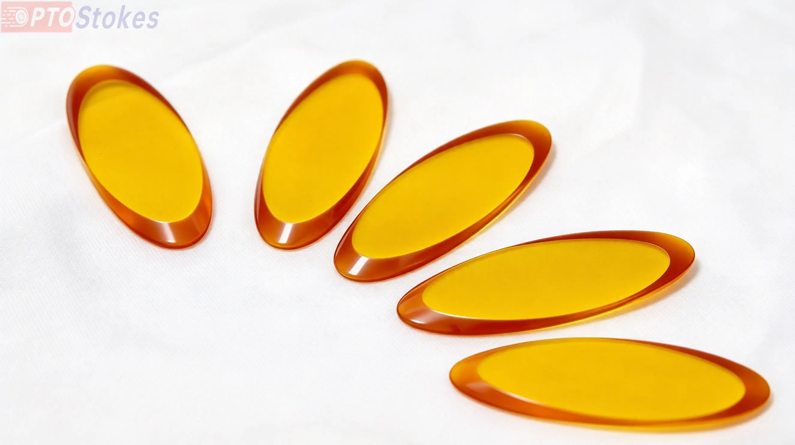
A round window in a beam path that turns through 45° wastes aperture. The projected opening becomes an ellipse, the corners of the round part sit outside the useful beam, and the mount has to grow to compensate. An elliptical zinc selenide flat is cut to match the projection instead, so the clear aperture stays circular at the working angle while the part stays inside a compact envelope.
This page covers the geometry behind that choice, what 45° incidence does to the beam, and the surface specifications that matter when the window sits in a CO2 laser path rather than in front of a detector.
Why the Aperture Is Elliptical
A circular beam meeting a flat at 45° illuminates an ellipse. The minor axis equals the beam diameter; the major axis equals the diameter divided by the cosine of the incidence angle. At 45° that factor is about 1.414, so a 25 mm beam footprint needs a window at least 25 mm by 35.4 mm to pass without clipping.
A round window of 35.4 mm diameter would work optically and is the usual compromise. It also costs 41% more area than necessary, adds mass at the edge of a moving assembly, and forces a larger mount—which is the real constraint in compact infrared heads and in laser cavities where the window sits close to the resonator optics.
The elliptical part keeps the same clear aperture with a smaller envelope. The trade-off is orientation: the major axis has to line up with the plane of incidence, so the drawing must mark it and the mount must key it.
What 45° Incidence Does to the Beam
Polarization
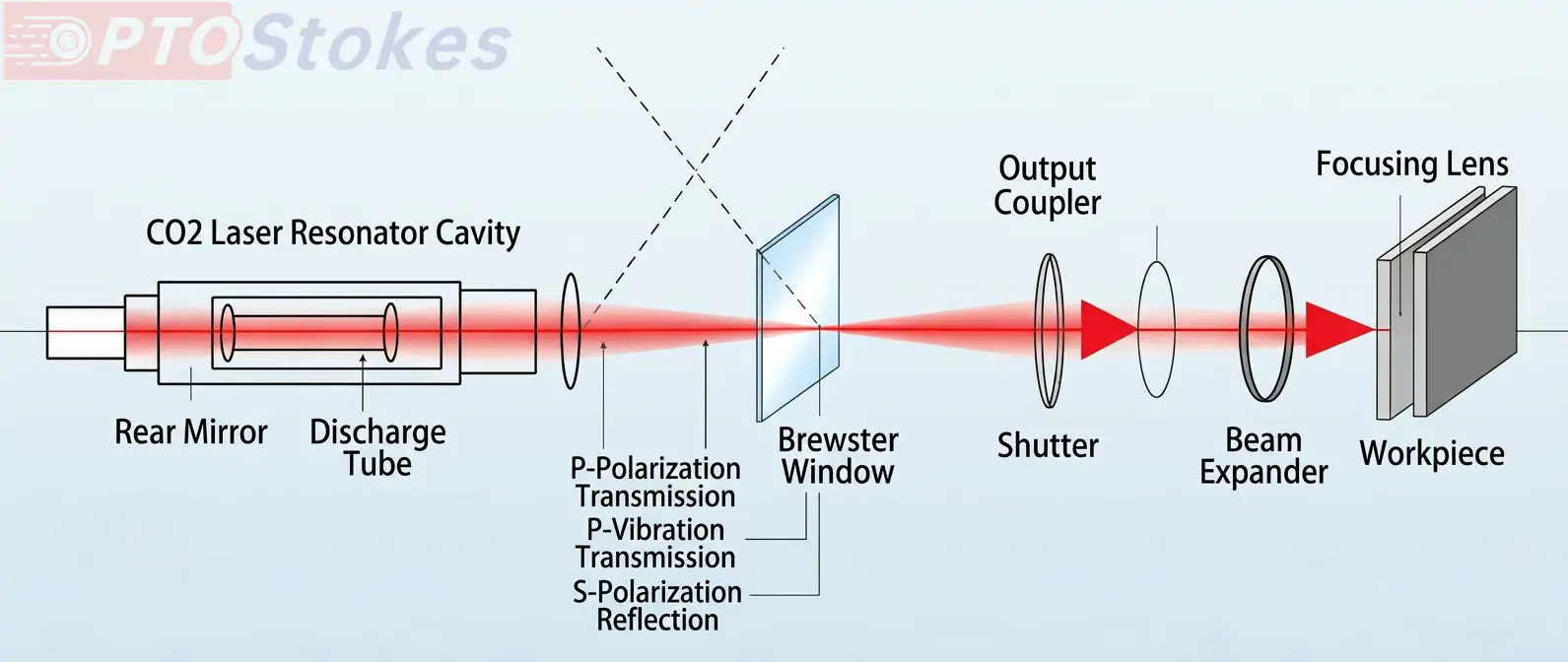
At 45° the s and p components see different reflection losses at each surface. That difference is polarization-dependent loss, and it is worth checking in any system that carries a defined polarization state through the window. It is not a polarizing function. If linearly polarized output is the design goal, the window has to sit at the Brewster angle, which for zinc selenide in air is near 67°, not 45°. A 45° window cannot be specified as a polarizer.
Ghost reflections
An uncoated zinc selenide surface returns a substantial fraction of the beam. At 45° that reflected light leaves at 90° to the input and usually lands somewhere useful—which is why the reflected beam appears in the layout and why the second-surface reflection becomes a displaced ghost rather than a simple back-reflection. The 15 arcsec wedge specified on these parts displaces the ghost, but it does not remove it. In an imaging path, or anywhere the ghost falls on a detector, an antireflection coating is the correct fix. Coating options for IR flats are compared in this review of AR and DLC coating selection for IR optics.
Beam deviation
A parallel flat does not deviate the transmitted beam, but it does offset it, and the offset scales with thickness and angle. Thickness is therefore a beam-steering parameter as well as a mechanical one, and it belongs on the drawing for that reason. A wedge of 15 arcsec contributes an additional angular error that is small in most layouts but not negligible in an interferometric one.
The Material
These windows are cut from CVD zinc selenide: polycrystalline, grown rather than melted, with the low scatter and low inclusion content that the deposition process allows. It transmits from the visible through roughly 21 µm, which covers the 10.6 µm CO2 line with margin and also covers the MWIR and LWIR bands used in thermal imaging.
Absorption at 10.6 µm is low in CVD material, and that is the reason zinc selenide is used for laser windows at all. Two caveats belong next to that statement. Zinc selenide is brittle and relatively soft, so it is not a shock-resistant material; survival depends on the mount and on handling rather than on the bulk. And under high average power, residual absorption produces a thermal gradient, which turns the window into a weak lens. At that point the design variables are thickness, coating absorption and cooling—not the transmission figure on the datasheet.
Specifications
| Parameter | Specification | Engineering note |
|---|---|---|
| Material | CVD zinc selenide, polycrystalline | Transmits from the visible to about 21 micro;m |
| Shape | Elliptical flat, designed for 45deg; incidence | Major axis = minor axis / cos 45deg;, roughly 1.414 times the minor axis |
| Surface quality | 40/20 scratch-dig | Applies per surface; inspection illuminance and magnification should be agreed |
| Wedge between faces | ≤ 15 arcsec | Displaces the second-surface ghost; does not replace an AR coating |
| Surface figure | Power ≤ 3 fringes, irregularity ≤ 0.5 fringe | Verified against a grade A reference flat; state the test wavelength |
| Coating | Uncoated as standard, AR available | Uncoated surfaces reflect a significant share of the beam at 45deg; |
| Orientation | Major axis marked | Without a keying mark the part can be installed 90° out and will clip the beam |
One note on figure. Three fringes of power and half a fringe of irregularity are appropriate for a protective or imaging window and for general beam transport. A window inside a laser resonator, or anywhere transmitted wavefront is specified, usually needs tighter figure and an explicit transmitted wavefront figure rather than a reflected-light surface specification. Those are different measurements and should not be substituted for one another.
Where the Part Fits
| Application | Why the elliptical flat suits it | What to watch |
|---|---|---|
| CO2 laser cavity end window and output protection window | Low absorption at 10.6 µm, and the elliptical outline clears a folded cavity without enlarging the housing | Thermal lensing at high average power; specify AR coating on both faces |
| FTIR and spectroscopy sample compartments | Broad transmission across the mid-IR, chemically stable in a purged enclosure | Cleanliness and handling, since the material scratches easily |
| Ellipsometry and polarimetry benches | Fixed 45° geometry matches the instrument layout | Polarization-dependent loss; the incidence angle has to be held accurately |
| Compact MWIR and LWIR imaging heads | Elliptical outline fits an inclined mechanical envelope | Ghost images; AR coating decides whether they matter |
When a Coated Part Is the Right Answer
A polished flat transmits. It does not split a beam to a design ratio, and it does not polarize. If the requirement is a defined R/T split at 45°, the correct component is a coated plate beamsplitter, where the ratio is a coating design value rather than a consequence of the substrate index. Our ZnSe beam splitters are specified that way, for example at R17/T83 at 45°. If the requirement is a clean window with controlled reflection loss, the flat on this page with an AR coating is the cheaper and simpler part—and the one that will not drift with polarization state.
The same distinction applies to the wider family: an infrared windows selection is built around transmission and sealing, while beam control is built around coating design.
Specifying an Elliptical Window
Most quoting delays on these parts come from an incomplete drawing rather than from the process. Six items resolve nearly all of them.
| Item | What to state |
|---|---|
| Clear aperture | Minor axis, or the beam diameter at the window |
| Incidence angle | 45° nominal, with the tolerance that matters to the layout |
| Thickness | Value and tolerance, since thickness sets the transmitted-beam offset |
| Surface figure and test method | Fringes at a stated wavelength, and whether transmitted wavefront is required |
| Coating | None, AR, or a defined reflectance; state the band and the faces to be coated |
| Orientation and edge | Where the major axis mark goes, and the chamfer permitted on the rim |
Request a Drawing Review
Elliptical windows are straightforward to make and easy to specify badly—usually through a missing incidence angle, an unstated coating band, or an orientation mark that never made it onto the drawing. Send the drawing, the wavelength range, the dimensions, the coating requirement, the operating conditions including power level and environment, and the quantity. We will confirm the geometry against your beam footprint and flag the specifications that will drive cost without improving performance.
Drawings and requirements can go to sales@iroptical.com, or through the contact form with the drawing attached. Where the angle, the band or the coating is still open, that is the right moment to raise it, not after the parts are cut.