
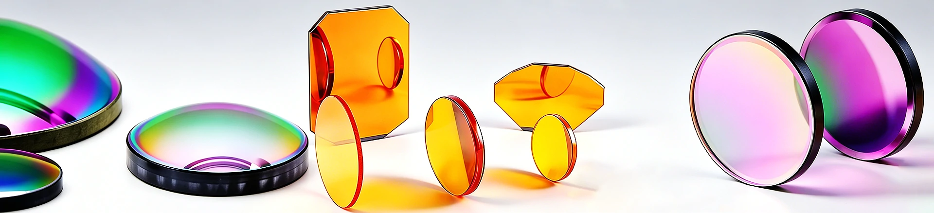
F/1.21 large aperture focusing, 10.6 μ m marking optical path
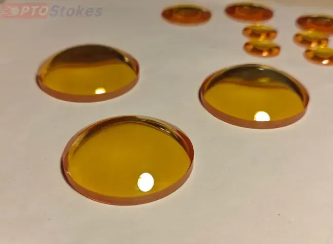
ZnSe plano convex focusing lens Dia25.4 mm EFL30.7 mm: for CO ₂ laser marking
ZnSe flat convex focusing lens, diameter 25.4 mm, EFL 30.7 mm ( F/1.2), suitable for CO ₂ laser marking focusing optical path. Data self consistent verification, customizable film system and surface shape according to drawings
Product Overview
This is a focusing lens for CO ₂ laser marking: CVD zinc selenide (ZnSe) flat convex structure, with a diameter of 25.4 mm (1 inch standard aperture) and an effective focal length of 30.7 mm, approximately F/1.21. The basis for determining that it is suitable for CO ₂ rather than other lasers is consistent with the window plate: ZnSe is only transparent in the infrared, not transparent in visible light and 1064 nm near-infrared, and can only be used for laser marking with a 10.6 μ m optical path. The combination of aperture and focal length provides a large relative aperture, which is a typical configuration for the marking head to compress the beam into a small spot. Similar lenses can be found in<a href=“ https://www.iroptical.com/IRLenses/ Infrared lens series
Technical specifications
| Project | Parameters | Description |
|---|---|---|
| Material | Zinc Selenide (ZnSe) | Infrared optical grade, 10.6 μ m low absorption |
| Effective focal length (EFL) | 30.7 mm | Input typo corrected (original 30.7 m) |
| Curvature radius (R) | 43.07 mm | Self consistency with EFL (f × (n-1)) |
| Diameter | 25.4 mm | 1-inch standard caliber |
| Center thickness/edge thickness | 3.3 mm/1.4 mm | Sagittal height 1.9 mm, consistent with R and caliber |
| Back focal length (BFL) | ≈ 28.8 mm | f-t (n-1)/n, calculated value |
| F-number | ≈ F/1.21 | EFL/diameter, calculated value |
| Coating | Confirm according to order | This application usually requires AR@10.6 μm |
| Surface shape/surface quality/chamfer | Confirmed according to order | Not given, drawing review |
Selection and deduction of F/1.2 focusing optical path
Selection example: The CO ₂ marking machine's vibrating mirror outputs a beam of about 20 mm, which is then focused by a focusing mirror to a hundred micron level spot and marked on the focal plane. F/1.21 compresses the beam quickly, and the depth of focus also becomes shorter - only in the sub millimeter range. When the workpiece height fluctuates or the focal plane is uneven, the edge spot quickly becomes larger, and the marking depth is uneven. The trade-off between flat convex structures here is very practical: low cost, simple assembly, and sufficient for applications such as marking that do not pursue diffraction limit spots; The cost is that the spherical aberration at F/1.2 is already quite considerable, and the light spot is larger than that of a curved moon mirror with the same parameters. The larger the scanning field, the thicker the edges. Applicable boundary: For scenarios with single point focusing, small field of view, and less stringent requirements for spot uniformity, flatness and convexity are cost-effective solutions; If the scanning area is large or the full area light spot is required to be consistent, the crescent or spherical aberration reduction structure should be evaluated. Write verification suggestions into the protocol - EFL measurement at the design wavelength, 10.6 μ m transmission curve after coating, and aging test at specified power.
Two places that are prone to misjudgment
The first one is to use a flat convex focusing mirror as an f-theta field mirror. After the head mounted galvanometer, a field lens (f-theta lens) is installed, which has an image height proportional to the scanning angle and a flat focal plane; Ordinary flat convex focusing mirrors do not have this design - the height is tangent to the angle, and the focal plane is still curved (Petzval curvature). The result of incorrect installation: defocusing of the scanning field edge marking and distortion of the graphic scale, which becomes more pronounced as the edge is closer. Discrimination method: Check if the specification book has the label "f-theta" and scanning format - this page does not have it, it is a single point focusing mirror, and after scanning with a vibrating mirror, a separate field mirror must be equipped.
The second is to ignore coating and thermal load. ZnSe bare surface single-sided reflection is about 17%, without coating 10.6 μ m anti reflective film, power loss of 30%, and back and forth reflection between mirror groups can easily burn adjacent lenses; The continuous absorption under the marking power also produces a thermal lens effect - the focus slowly drifts with temperature rise, and the position of the light spot quietly changes after several hours of continuous marking. Purchase order clearly states AR@10.6 μ m and membrane surface number, acceptance check the measured transmittance curve; Leave a focus margin for applications that are sensitive to alignment. I also need to add a sentence about the unique failure of marking environment: smoke and dust. The smoke and dust generated by marking will deposit on the convex surface (facing the incident side), and the deposited layer will continue to absorb laser and be heated. The film layer may be eroded and produce pitting, and the entire piece may be scrapped - this is the most common practical method for marking focusing lenses, much more common than scratching. The countermeasure is to install air curtains or blow configurations, regularly shut down for mirror inspection, and replace the film immediately if any spots are found. Don't wait for it to break in the light path.
Customization and Service
Diameter, focal length, center thickness, chamfer and installation surface shall be processed according to the drawings; The membrane system is designed according to the working wavelength (10.6 μ m single point or broadband). For projects that require high consistency of large scanning or full field light spots, crescent shapes, spherical aberration reduction combinations, or f-theta field mirrors can be evaluated as alternatives to flat convex ones. Horizontal comparison of materials can be found in<a ref=“ https://www.iroptical.com/materials/ Infrared Material Page
Information required for inquiry
Location of use (single point focusing or mirror scanning), operating wavelength, EFL and BFL, incident beam diameter, surface shape and quality, coating indicators and quantity, with drawings provided as the fastest. Sent to sales@iroptical.com , Or through<a ref=“ https://www.iroptical.com/contact/ Inquiry pageSubmit. The specific values for coating, surface shape, and surface quality are not listed on this page and need to be reviewed and confirmed according to the drawings; If you are a scanning and marking application, please also inform us of the format size, and we will re evaluate according to the specifications of the field lens.