
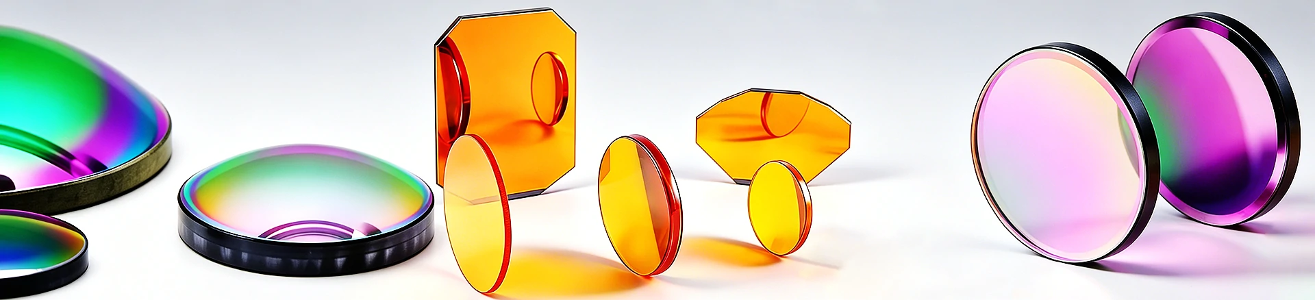

ZnSe flat convex lens Dia25.4mm EFL40mm: LWIR focusing lens, AR 8–12 μm
ZnSe flat convex lens, diameter 12.70 mm, EFL 40 mm, IR AR 8-12 μ m anti reflection, suitable for long wave infrared focusing optical path. Complete specification data, supporting customized drawings
Product Overview
This is a long wave infrared focusing lens: CVD zinc selenide (ZnSe) plano convex structure, diameter 25.4 mm (1/2 inch standard aperture), effective focal length 40 mm, approximately F/3.15, double-sided IR AR anti reflective coverage 8-12 μ m. Its role in the optical path is focusing or collimation - converging parallel long wave beams onto the detector or sample - rather than a transparent window: the window requires uniform high transmittance, while the lens requires focal position and aberration control, which cannot be interchanged in the system. Similar lenses can be found in<a href=“ https://www.iroptical.com/IRLenses/ Infrared lens series
Technical specifications
| Project | Parameters | Description |
|---|---|---|
| Material | Zinc Selenide (ZnSe) | Infrared Optical Grade |
| Diameter | 25.4mm | 1/2-inch standard caliber, compatible with universal frame |
| Effective focal length (EFL) | 40.00 mm | Nominal at design wavelength |
| Curvature radius (R) | 56.11 mm | Convex surface, self consistent with EFL (f × (n-1)) |
| Back focal length (BFL) | 39.00 mm | Back vertex to focal point |
| Center thickness/edge thickness | 2.40 mm/2.00 mm | Consistent with R and caliber rise |
| F-number | ≈ F/3.15 | EFL/diameter, calculated value |
| Coating | IR AR 8-12 μ m | Single/Double sided according to order confirmation |
| Surface shape/surface quality/chamfer | Confirmed according to order | Not given, drawing review |
Selection and deduction of LWIR focusing optical path
Selection example: A set of 8-12 μ m long wave infrared systems requires focusing the collimated beam onto the detector or collimating and expanding the point light source. When used in FTIR, the corresponding position is usually the sample chamber spotlight or detector coupling - the former has loose requirements for the light spot, while the latter is sensitive to the focal length tolerance. When the same lens is installed in different positions, the acceptance focus varies. The flat convex structure has a fixed usage rule here: when focusing on an infinitely distant target, the convex surface faces parallel light, and when collimating a point light source, the plane side faces the light source - this ensures the best symmetry of the main surface position and minimizes spherical aberration; The focal length remains unchanged when reversed, but the aberration noticeably deteriorates. Choice point: 8-12 μ m AR means this is a band limiting component - ZnSe has a refractive index of about 2.4, uncoated single-sided reflection is about 17%, and double-sided bare transmission is about 70%; After AR, the long wavelength band is transmitted up to 90%, but the reflection loss in the 2.5-8 μ m range rebounds. If the system wants to cover the entire infrared band, this film system is not the correct choice and needs to be discussed again. F/3.15 belongs to the category of medium to large relative aperture, and the spherical aberration of flatness and convexity cannot be ignored. For applications that are sensitive to the size of the light spot, the diffuse spot should be checked during the design stage, rather than being checked after installation. Attention should also be paid to temperature drift: the dn/dT of ZnSe is about 60 × 10 ⁻⁶/K (typical value of the material). Calculated according to f=R/(n-1), the focus drift of 40mm focal length is sub millimeter level when the ambient temperature changes by tens of degrees. For detector coupling applications that are sensitive to alignment, a focusing margin should be left. Verification suggestions should be included in the protocol: EFL measurement at the design wavelength, 8-12 μ m transmission curve after coating, and surface PV
Two places that are prone to misjudgment
The first one is to only look at the focal length and not the film system. The ZnSe lens labeled "EFL 40mm" with 8-12 μ m AR and 3-5 μ m AR are two different components: the wavelength band is incorrect, the transmittance drops by 30%, and ghost images are generated inside the cavity. The purchase order must clearly state the design band and number of film surfaces (single-sided or double-sided AR). Double sided anti reflection is about 20% more transparent than single-sided, and the price and acceptance criteria are different.
The second is to use the lens as a window or the window as a lens. The window is inspected based on "parallel plane, uniform transmission", while the lens is inspected based on "focal length, surface shape, aberration". The tolerance systems of the two are completely different. The tolerance meanings of the planar and convex sides of a plano convex lens are different - the planar side considers parallelism and surface shape, while the convex side considers curvature radius and irregularity - before placing an order, it is much more effective to separate the requirements for both sides than to write a general "surface shape".
Customization and Service
Diameter, focal length, center thickness, chamfer and installation surface shall be processed according to the drawings; The membrane system is designed according to the working wavelength range (3-5 μ m, 8-12 μ m, or specified single point). When larger relative aperture or higher image quality requirements are met, crescent or non spherical structures can be evaluated as alternatives to plano convex structures. Horizontal comparison of materials can be found in<a ref=“ https://www.iroptical.com/materials/ Infrared Material Page
Information required for inquiry
Design the frequency band and number of film surfaces, EFL and BFL, diameter and center thickness, surface shape and quality, use of optical path (focusing or collimation, convex orientation) and quantity, and attach the drawings as soon as possible. Sent to sales@iroptical.com , Or through<a ref=“ https://www.iroptical.com/contact/ Inquiry pageSubmit. The specific values for the shape, surface quality, and number of coated surfaces on this page are not listed and need to be reviewed and confirmed according to the drawings.