
Why Is Your CO2 Laser Power Dropping? Check Cavity Mirrors?
Understanding CO₂ Laser Cavity Mirror Failures & Performance Impacts
In CO₂ laser equipment maintenance and laser tube manufacturing, power attenuation, beam divergence, and premature lens failure are the three most common operational issues. Many practitioners first attribute these problems to laser tube aging, suboptimal gas mixing, or power supply faults, while overlooking the hidden defects in cavity mirrors—the core components of the resonator.
The CO₂ laser resonator consists of a total reflective rear mirror and an output coupler. Their curvature matching, coating transmittance, and surface figure accuracy directly determine laser output power, beam mode quality, and overall service life. Field statistics show that over 90% of non-consumable power drops and mode degradation stem from insufficient machining precision, poor coating quality, or improper substrate selection of cavity reflective mirrors and output couplers.
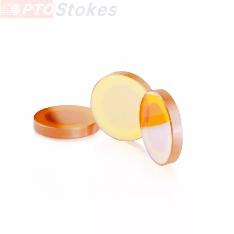
iroptical offers a full range of CO₂ laser cavity mirrors, including silicon-based reflectors with 10.6μm high-reflection dielectric coatings and zinc selenide output couplers with various transmittance options. Standard specifications are kept in stock, while custom non-standard configurations are fully supported.
Surface Figure Error: The Hidden Driver of Resonator Mode Degradation
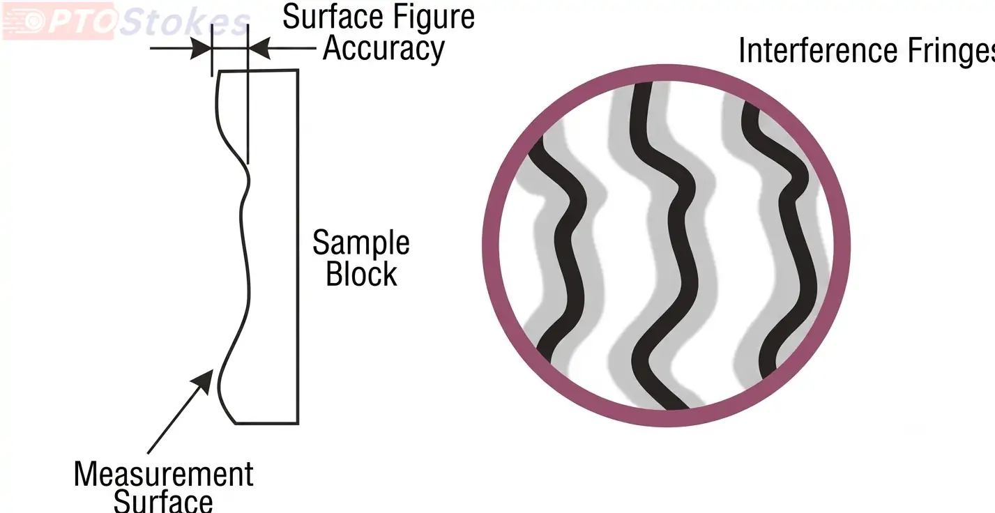
A CO₂ laser resonator relies on the curvature of two end mirrors to establish a stable optical field. Surface figure errors on mirror surfaces directly introduce wavefront distortion and disrupt resonator mode matching. Surface figure accuracy is typically measured by PV (peak-to-valley) value, referenced to the operating wavelength λ (10.6μm), and its grade directly defines the upper limit of resonator mode performance.
Typical Failure Symptoms
• Acceptable beam profile during initial commissioning, but gradual beam divergence and edge tailing after hundreds of operating hours, leading to increased dross on cut edges and uneven engraving depth
• Output power variation exceeding 15% across same-batch laser tubes, requiring lengthy per-unit alignment and resulting in poor batch consistency
• Normal beam profile at low power, but rapid beam distortion and reduced mode stability once power reaches rated levels
Quantified Standards & Troubleshooting Methods
Surface figure accuracy is generally classified into commercial-grade and high-precision grades. Commercial-grade cavity mirrors typically have a PV value of λ/2 to λ/4, meeting basic requirements for rough processing equipment but exhibiting noticeable mode drift under long-term high-power operation. High-precision cavity mirrors can reach a PV value of λ/10, delivering minimal wavefront distortion, stable resonator modes, and a high fundamental mode ratio.
Based on resonator diffraction theory, every λ/4 of surface PV error introduced by the mirror increases single-pass diffraction loss by approximately 15% to 20%, corresponding to an 8% to 12% drop in output power, along with a significant rise in higher-order transverse mode proportion.
| Accuracy Grade | Surface Figure PV Value | Typical Application | Power Stability |
|---|---|---|---|
| Commercial Grade | λ/2 – λ/4 | Low-power rough processing equipment | Noticeable drift under sustained high power |
| High Precision Grade | ≤ λ/10 | High-precision cutting, medical and industrial systems | Stable output over tens of thousands of operating hours |
For troubleshooting, use a laser interferometer to inspect surface figure. A PV value exceeding the design tolerance by 20% or more confirms surface figure over-tolerance. In addition, insufficient mirror thickness or excessive clamping stress can cause secondary surface deformation after assembly. For example, a 4.5mm thick silicon reflector may introduce additional surface distortion if the clamping ring applies uneven force. This is why high-power folded cavities above 300W typically use 10mm thick silicon mirrors to suppress clamping deformation via improved structural rigidity.
Our high-precision cavity mirrors achieve a surface figure PV value of up to λ/10 with a surface quality grade of 10-5, delivering minimal wavefront distortion and stable resonator performance for tens of thousands of hours. Backed by a full set of high-precision inspection equipment, every cavity mirror undergoes full-dimensional testing covering surface figure, angle, transmittance, and laser damage threshold to ensure performance falls within design tolerances.
Coating Process Defects: The Primary Cause of Film Failure at High Temperatures
The resonator cavity operates long-term in a glow discharge, high-temperature plasma environment. Cavity mirror coatings must withstand both high-power laser irradiation and chemical erosion. Under high power density, thermal distortion and thermal damage to output windows and total reflectors are often the key technical limitations to increasing laser power and improving beam quality. Incomplete substrate cleaning before coating, poor coating stress matching, or low-purity coating materials will gradually lead to coating oxidation, peeling, and ablation, causing reflectance/transmittance to deviate from design values and ultimately resulting in continuous power attenuation.
Typical Coating Failure Symptoms
• Hazy whitening, spot peeling, or film flaking on the mirror surface, with visible coating damage when viewed against light
• Steady month-over-month output power decline with no sudden drop, and no significant improvement after mirror cleaning
• Sudden power drop within a short time under high-power operation, with ablation spots on the mirror surface and irregular dark areas in the beam profile in severe cases
Core Coating Reliability Metrics
Coating reliability can be evaluated against four key indicators:
| Metric | Acceptance Standard | Impact of Non-Compliance |
|---|---|---|
| Reflectance Consistency | ≤ ±0.1% deviation at 10.6μm across same-batch mirrors | High attenuation variation and poor batch consistency over time |
| Laser Damage Threshold | ≥ 10kW/cm² CW; ≥ 15J/cm² pulse | Coating breakdown, pinholes and premature failure |
| Environmental Durability | No peeling, flaking or cracking after -40°C to 85°C thermal cycling and adhesion test | Coating degradation under harsh operating conditions |
| Spectral Thermal Drift | ≤ 0.002nm/°C center wavelength shift | Sharp increase in cavity loss as operating point deviates from coating curve |
For troubleshooting, first visually inspect coating integrity, then measure actual transmittance/reflectance with an infrared spectrophotometer. A deviation of more than 2% from the nominal value indicates coating failure. Flat reflectors in high-power folded cavity models bear the highest thermal load and are the most prone to coating failure, so they should be inspected first.
We operate an in-house coating production line, offering AR coating, high-reflection coating, filter coating, polarizing coating, beam splitter coating, DLC coating and high laser damage threshold coating options. For 10.6μm CO2 laser systems, we provide two high-reflection dielectric coating solutions: black coating and gold coating. The black coating delivers ≥ 99.8% reflectance for minimal cavity loss, while the gold coating combines high reflection at 10.6μm with 650nm red light visibility for convenient optical alignment and equipment commissioning. Our coatings resist oxidation and peeling under the high-temperature operating environment of the resonator, delivering extended service life.
Our ZnSe optics portfolio is engineered to complement cavity mirror assemblies, with matched material and coating specifications for complete optical chain performance. For beam delivery systems, our precision CVD ZnSe lenses ensure consistent beam quality from resonator to workpiece.
Get Customized Cavity Mirror Solutions for Your CO₂ Laser Systems
For R&D engineers, inconsistent mode quality and unexpected power drift can delay product validation and increase debugging cycles. For purchasing managers, unstable batch quality and unpredictable lead times raise production costs and inventory risks. For technical decision-makers, short component service life and frequent maintenance directly impact total cost of ownership and equipment uptime.
iroptical addresses these pain points with in-stock standard cavity mirrors for fast delivery and custom-engineered solutions tailored to your exact specifications, supported by full-process quality control and engineering review. Whether you need prototype samples for validation or bulk production with consistent quality, our team provides responsive technical support and transparent lead times.
Contact us at sales@iroptical.com with your drawing, wavelength requirements and tolerance specifications to receive a technical review and formal quotation.