
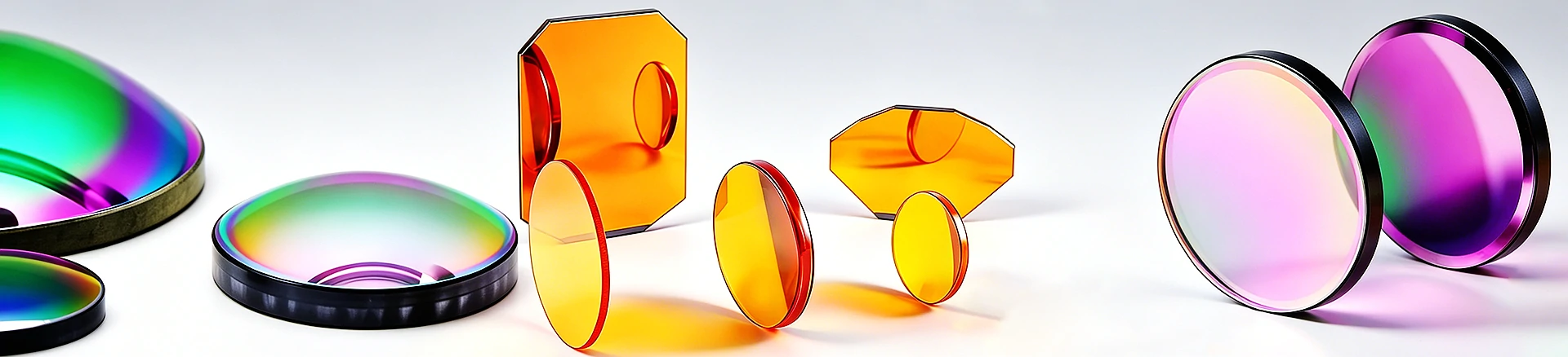
F/2.54 telephoto focusing, large format telephoto depth
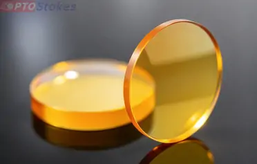
ZnSe plano convex focusing lens Dia25.4 mm EFL64.4 mm: for CO ₂ laser marking (telephoto type)
ZnSe flat convex focusing lens, diameter 25.4 mm, EFL 64.4 mm ( F/2.5), with larger spot size and longer focal depth, suitable for large format CO ₂ laser marking. Specification self consistent verification, customizable film surface shape
Product Overview
This is a focusing lens for CO ₂ laser marking: CVD zinc selenide (ZnSe) flat convex structure, with a diameter of 25.4 mm (1 inch standard aperture) and an effective focal length of 64.4 mm, approximately F/2.54. Compared with short focal length focusing lenses (such as EFL 30.7 mm), doubling the focal length is not simply about "shooting farther" - the spot, depth of focus, power density, and scanning format all change together, and selecting the wrong direction will result in an overall decline in marking quality. Its CO ₂ band adaptability is consistent with all ZnSe marking components: ZnSe only transmits infrared, and the marking optical path can only be 10.6 μ m. Similar lenses can be found in<a href=“ https://www.iroptical.com/IRLenses/ Infrared lens series
Technical specifications
| Project | Parameters | Description |
|---|---|---|
| Material | Zinc Selenide (ZnSe) | Infrared optical grade, 10.6 μ m low absorption |
| Effective focal length (EFL) | 64.4 mm | Self consistent with R (f × (n-1)) |
| Curvature radius (R) | 90.4 mm | Convex surface |
| Diameter | 25.4 mm | 1-inch standard caliber |
| Center thickness/edge thickness | 2.9 mm/2.0 mm | Vector height 0.9 mm, consistent with R and caliber |
| Back focal length (BFL) | ≈ 62.7 mm | f-t (n-1)/n, calculated value |
| F-number | ≈ F/2.54 | EFL/diameter, calculated value |
| Coating | Confirm according to order | This application usually requires AR@10.6 μm |
| Surface shape/surface quality/chamfer | Confirmed according to order | Not given, drawing review |

Double focal length, where is the trade-off: selection deduction
Selection example: Choose between two lenses of EFL 30.7 mm and 64.4 mm for the same CO ₂ marking head. According to the F-number calculation, the spot diameter is enlarged by about 2.1 times, the diffraction focal depth is enlarged by about 4.4 times (calculated value, actually more affected by spherical aberration), and the power density at the focal point decreases by about 4 times. In terms of marking effect: telephoto lens provides a larger marking area and longer focal depth - in situations where the workpiece is uneven and the height fluctuates, the edges are not easily defocused, which is the real advantage of telephoto lens; The cost is that the power density per unit area is low, and for the same marking depth, either the power is increased or the marking is repeated several times, resulting in a decrease in efficiency. Applicable boundaries: For thin coating marking, large format QR codes, and production lines that are uncertain about the flatness of workpieces, telephoto is a reasonable choice; In situations where deep carving, high reflectivity materials, or narrow cutting seams are required, short focal length is more suitable. The two are not a matter of superiority or inferiority, but rather a matching relationship of working conditions. Verification suggestions should be included in the protocol - EFL measurement at the design wavelength, 10.6 μ m transmission curve after coating, and sampling of marking depth under actual working conditions.
Two places that are prone to misjudgment
The first one is to use BFL as the working distance. 62.7 mm is the distance from the back vertex to the focal point, not the position where you can place the workpiece - there are usually protective lenses, air curtains, or blowing structures occupying a few millimeters in the marking head, and the actual working distance is shorter than BFL. Using BFL directly to measure the height of the workpiece, the overall focus of the machine is offset, and the reason for the uneven depth cannot be found. Correct approach: Deduct the thickness of the intermediate components according to the overall machine drawing, or calibrate the measured focal plane after installation, and write the calibration value into the operation manual.
The second option is to select the focal length based solely on the size of the frame. It's true that the telephoto lens has a larger coverage, but as the coverage increases, the spot size also increases, resulting in a decrease in power density per unit area and a corresponding increase in marking speed and depth. When selecting the focal length, three things should be checked together: frame size, spot size, and power density. Any missing one will result in rework such as "enough frame size, insufficient depth" or "too deep depth, edge defocusing".
Customization and Service
Diameter, focal length, center thickness, chamfer and installation surface shall be processed according to the drawings; The membrane system is designed according to the working wavelength (10.6 μ m single point or broadband). The 25.4mm standard caliber also has a purchasing value layer: focusing lenses of different EFLs under the same caliber share the same set of mirror frames. If the production line needs to switch between large format shallow marking and small format deep marking, two lenses of the same caliber with different focal lengths can be replaced online without changing the overall structure - this is also the significance of making the focal length into a series of specifications. Please pay attention to the field mirror requirements for scanning applications after galvanometer scanning - flat convex focusing mirrors and f-theta field mirrors are two types of devices, and when the requirements for amplitude and linearity are high, the field mirror or meniscus structure should be evaluated. Horizontal comparison of materials can be found in<a ref=“ https://www.iroptical.com/materials/ Infrared Material Page
Information required for inquiry
Position of use (single point focusing or scanning after galvanometer), working wavelength, EFL and BFL, incident beam diameter, target spot and size, coating indicators and quantity, attached drawings are the fastest. Sent to sales@iroptical.com , Or through<a ref=“ https://www.iroptical.com/contact/ Inquiry pageSubmit. The specific values for coating, surface shape, and surface quality are not listed on this page and need to be reviewed and confirmed according to the drawings.