
10-14 μ m passband, 400 nm-9.6 μ m cutoff OD>2
LP9900 Long Pass Filter: ZnSe Substrate, Used for FTIR Infrared Spectrometer
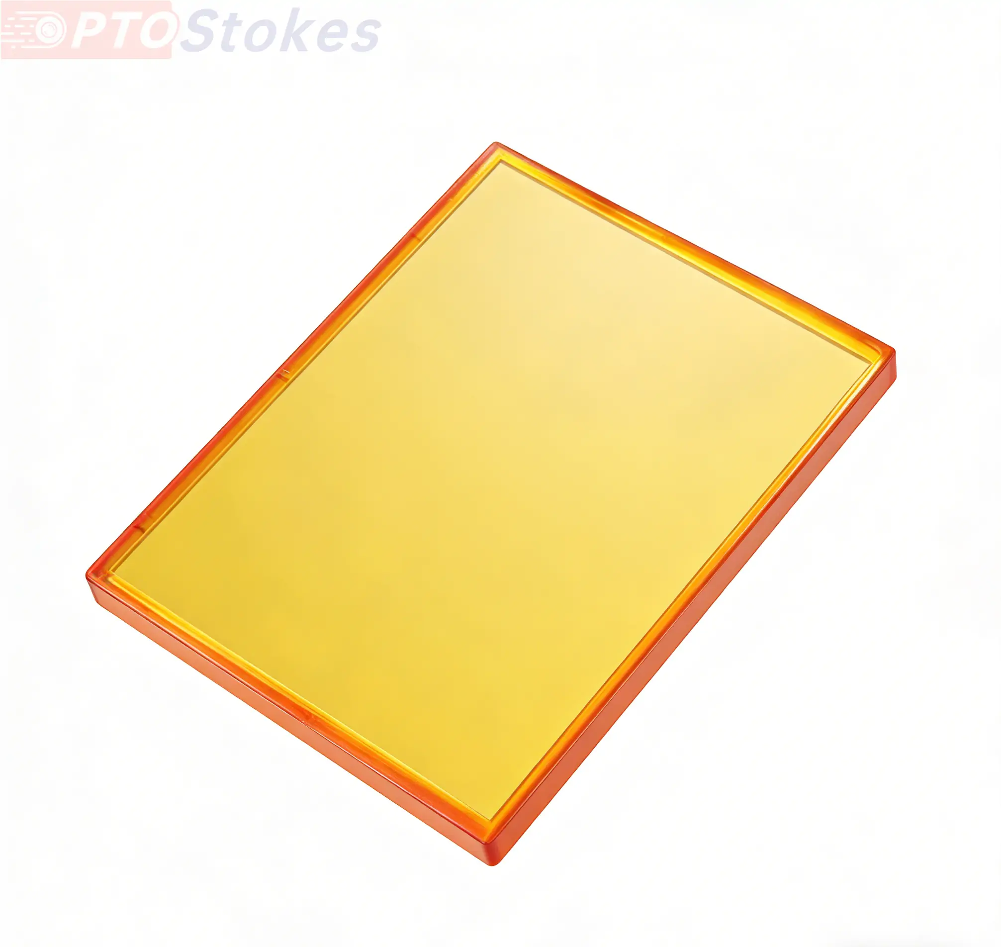
LP9900 nm long pass filter, ZnSe substrate 0.5 mm, passband T>90% at 10.15-14.3 μ m, cutoff OD>2 at 400 nm-9.6 μ m, used at 0 C, compatible with FTIR infrared spectrometer.
Product Overview
This is a long pass filter installed in the optical path of a Fourier transform infrared spectrometer: the substrate is a 0.5mm thin CVD ZnSe, and the long band T is greater than or equal to 10.15-14.3 μ m (approximately 985-700 cm ⁻¹); 90% pass, all visible, near-infrared, and mid infrared wavelengths from 400 nm to 9.6 μ m are cut off (OD>2), designed for 0 ° vertical incidence. Its function is not to "transmit light", but to block the short wave stray light and leakage in the spectrometer from the detector - the value of such filters lies entirely in the cleanliness of the cut-off and the stability of the edge position. Horizontal comparison of materials can be found in<a ref=“ https://www.iroptical.com/materials/ Infrared Material Page
Technical specifications
LP9900 nm ZnSe Long Pass Filter: Specifications Confirmed
| Project | Parameters | Description |
|---|---|---|
| Type | Long pass filter, LP9900 nm | Interference film type |
| Substrate/Thickness | CVD ZnSe, 0.5 mm | Thin film, prone to warping after coating |
| passband | 10150-14300 nm, T>; 90% | Approximately 985-700 cm ⁻¹ |
| Cut off range | 400-9600 nm, OD>; 2 | Transmittance<1% |
| Transition band | 9600-10150 nm | Defined by passband and cutoff segment |
| Design incidence angle | 0 ° | Vertical incidence |
| Dimensions | Confirm according to the drawing | Not given |
| Definition of edge wavelength/steepness of cutoff edge/passband ripple | Confirmed according to order | Not given, review before quotation |
Selection deduction in FTIR
Selection example: FTIR with a long wave detector is used to measure the 700-985 cm ⁻¹ range. Energy outside the detection range - short wave leakage caused by the efficiency curve of the beam splitter and thermal radiation from optical components - will enter the spectrum in the form of stray light, reducing the apparent absorbance of weak peaks. LP9900 shifts 400 nm-9.6 μ m to OD>; 2. Leakage pressure within 1%, T>within the passband; 90% hardly loses signal. Choice point: T>; The number 90% is not for nothing - the refractive index of ZnSe is about 2.4, single-sided reflection is about 17%, double-sided bare transmission is only 70%, and a passband of over 90% means that the back must synchronously increase transmission, and the number of film layers and stress increase accordingly; The 0.5mm thin substrate is designed to reduce internal absorption and leave room for long wavelength passband, but the thin film is prone to warping after coating, and the surface shape and parallelism must be inspected after coating. Applicable boundary: OD>; 2 is the cut-off for the suppression level of stray light, not the deep cut-off - in quantitative analysis, small peaks near strong peaks are contaminated by 1% leakage, and that scenario requires an OD4 or higher. Verification suggestions should be included in the protocol: the measured cut-off curve of 0 ° and the specified off-axis angle, the T-curve of the passband, and the shape record after coating.
Two places that are prone to misjudgment
The first step is to install a filter with a 0 ° design into the converging light path. The edge wavelength of the interference filter shifts blue with increasing incident angle, and a 0 ° design means that the index only holds true under near vertical incidence; In the converging light path in front of the detector, the incident angle of the edge field of view can reach more than ten degrees, and the cutoff edge is offset as a whole. The position near the edge of the cutoff segment begins to leak, and the spectrum shows a "raised tail" at the cutoff end, which changes with the aperture expansion and contraction. Correct approach: Use in parallel light segment; When installing at the convergence position, it is necessary to re adjust the indicators and redesign the film system according to the maximum incident angle, rather than rigidly using the 0 ° indicator.
The second one is to set OD>; 2. When used for deep cut-off. OD> The transmittance is less than 1%, which is sufficient to block stray light; If used for weak absorption quantification or scenarios requiring 10 ⁻⁴ level suppression, a 1% leakage is sufficient to overwhelm the signal. The cut-off depth should be discussed based on the application, do not use an OD value to spread it around. Similarly, do not ignore temperature: the edge position of the interference film drifts with temperature, and fluctuations of a few degrees inside the spectrometer can cause the edge to move by several nanometers. Accurate applications at the edge require asking the manufacturer for temperature drift data.
Customization and Service
The installation direction should not be reversed: the interference film should face the short wave side (incident direction), and the back anti reflection surface should face the detector. After the film surface is reversed, the cutoff and passband indicators do not hold - the lack of directional markings on the filter is the source of controversy. It is recommended that the manufacturer mark the edge and indicate it on the drawing. The interference film surface is afraid of rubbing, and cleaning requires blowing, washing, and suction operations, which are different from the maintenance requirements for the polished surface on the back. The edge wavelength, passband range, cutoff depth, aperture, and substrate thickness are all customized according to requirements; The surface shape control and low stress film system after ZnSe thin film coating are the focus of the process. ZnSe reflective filters (attenuators) on the same site belong to another category of devices, see<a href=“ https://www.iroptical.com/znse-reflective/ Reflective filter series
Information required for inquiry
The definition of edge wavelength (50% point or specified transmittance point), passband and cutoff indicators, use of optical path (parallel or convergent, maximum incident angle), size and quantity, please refer to the attached drawing for the fastest. Sent to sales@iroptical.com , Or through<a ref=“ https://www.iroptical.com/contact/ Inquiry pageSubmit. The specific values for edge definition, cutoff edge steepness, passband ripple, and dimensions are not listed on this page and need to be reviewed and confirmed according to the drawings.