
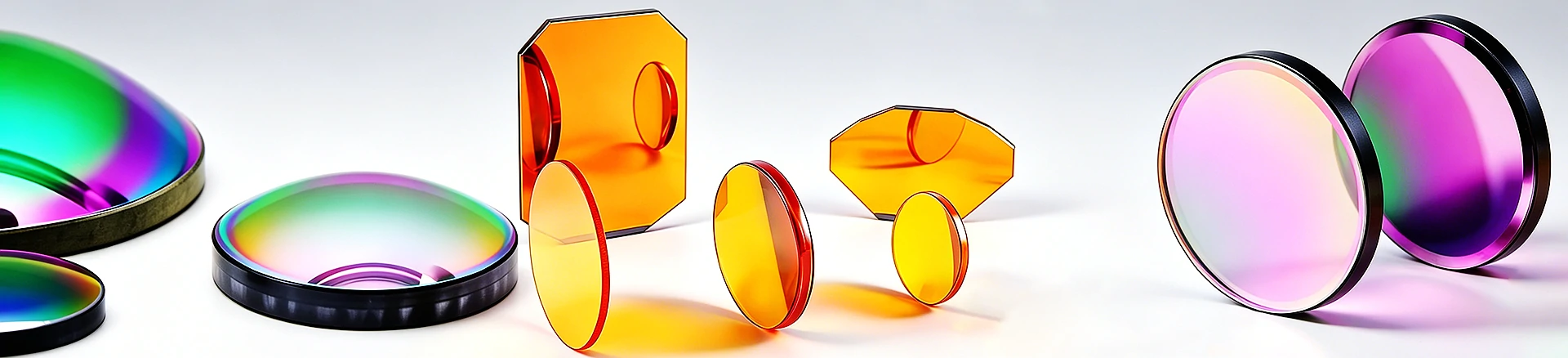

0.6-21 μ m transmission, large aperture long strip infrared window
CVD ZnSe large aperture rectangular window 170 × 50 × 5.8 mm
170 50 5.8 mm CVD zinc selenide (ZnSe) large aperture long window, 0.6-21 μ m transmission, non hygroscopic, suitable for large spot laser and thermal imaging optical paths. Wedge angle, coating and surface tolerance can be customized acc
Product Overview
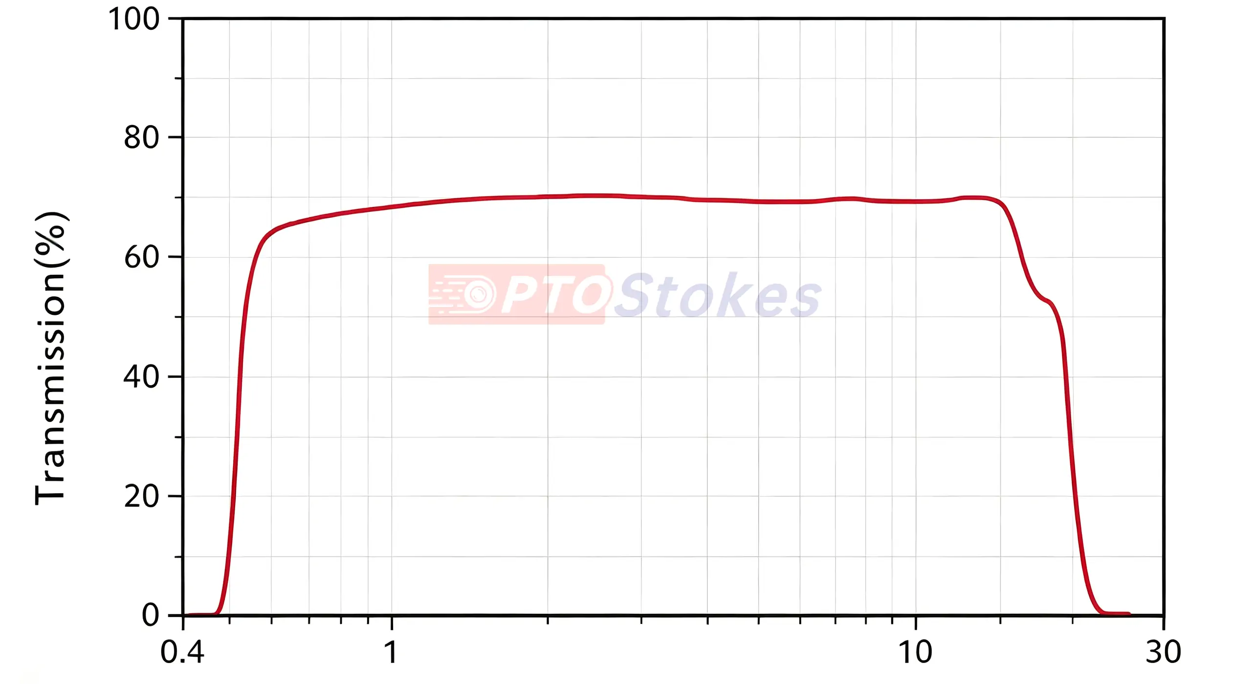
This is a large-diameter rectangular CVD zinc selenide (ZnSe) window, measuring 170 × 50 mm, with a thickness of 5.8 mm, transmitting 0.6-21 μ m, and not absorbing moisture. This specification does not specify the specific purpose, and is defined according to the general working conditions of large aperture infrared windows: large spot CO ₂ laser transmission, large field of view thermal imaging window, and wide optical path detection are all within their capabilities, but the requirements for thickness, surface shape, and coating are not the same among the three - this is exactly the part that needs to be explained before placing the order. Similar standard components can be found in<a ref=“ https://www.iroptical.com/IRWindows/ Infrared Window Series
Technical specifications
| Project | Parameters | Description |
|---|---|---|
| Materials/Processes | Zinc Selenide (ZnSe), CVD | Optical grade Polycrystalline |
| Dimensions | Rectangular 170 × 50 mm | Length to width ratio of approximately 3.4:1 |
| Thickness | 5.8 mm | Determine the interference ripple period |
| Transmission range | 0.6-21 μ m | Typical values of materials |
| Refractive index | ≈ 2.4 (10 μ m) | Typical values of materials |
| Uncoated transmittance | About 70% | Reflection on both sides is about 17%, Fresnel calculation |
| Knoop hardness | ≈ 105 kg/mm ² | Soft material, easily scratched by dry rubbing |
| Parallelism/surface shape/surface quality/coating | Confirmed according to order | Not given, drawing review is required before quotation |
Selection and deduction of large spot CO ₂ optical path
Selection example: A large spot CO ₂ system, the expanded beam enters the processing area through a window, which is responsible for blocking splashing and pollution. The reason why we chose ZnSe is that its absorption coefficient at 10.6 μ m is extremely low (typical<0.0005 cm ⁻¹), and the thermal load margin is wider than that of Ge; A thickness of 5.8 mm is a reasonable rigid ratio for a 170 mm long edge, which is not easily deformed after clamping. Choice point: It must be coated with 10.6 μ m anti reflective coating. If the reflection on both sides is not treated, light traveling back and forth between the mirror groups will form ghost images and burn adjacent lenses. Applicable boundary: If the window is close to the focal point or directly facing the high anti material return light, it should be inspected according to the laser level damage threshold rather than the window level. Write verification suggestions into the protocol - measured transmission curve at 10.6 μ m after plating, recording of the entire surface shape, and high-power aging pilot.
Two places that are prone to misjudgment
The first one is that thickness is treated as a pure structural parameter. A 5.8mm parallel plane window forms a Fabry Perot cavity, and according to 1/(2nt) calculation, the comb interference ripple period is approximately 0.36 cm ⁻¹ (theoretical calculation value). When the instrument resolution is better than this cycle (such as high-resolution FTIR), ripples will appear on the baseline; The coarse scanning mode (4 cm ⁻¹) is averaged out. So the phenomenon of "two instruments measuring two baselines in the same window" often appears, which is mistakenly judged as a difference in material batches. Discrimination method: Rescan the background with an empty light path, tilt the window by 2-3 °, and observe whether the ripple shifts. Countermeasure: Choose the version with wedge angles or use it tilted during installation. By the way, let me clarify the boundary: in the 10.6 μ m single line laser path, the same interference effect is manifested as a fixed transmittance shift rather than ripple, with a magnitude of only a few percent; Only for broadband scanning purposes do we need to pay for the wedge angle to eliminate ripple. The use once again determines whether 5.8 mm is a problem.
The second one is to only inspect the center point of large-diameter parts. There is residual stress in CVD ZnSe, and the stress zone spanned by the 170 mm long edge is larger than that of small-diameter parts. After polishing, stress rebalancing will cause the surface shape to curl back; Single point or single diagonal detection cannot detect collapsed edges and corners. The consequences are most direct in the converging light path: wavefront degradation at the edge of the field of view, decreased image quality, and only discovered when installed. The correct approach is to write the acceptance clause for the entire surface PV and the range inside the surface, and attach a full aperture interference diagram with the goods; Use surface pressure or elastic compression for clamping to avoid contact between screw points.
Customization and Service
The size, thickness, wedge angle, chamfer, and installation hole position shall be processed according to the drawings; Coating options include infrared broadband anti reflection or 10.6 μ m single point anti reflection, and the film system is evaluated based on the working band. The surface shape control and low stress polishing of large-diameter rectangular windows are the key processes. In terms of use and maintenance, the 170mm large surface is a soft material, and it is recommended to prioritize blowing, washing, and vacuuming to avoid dry wiping the entire surface - scratches left by a single wipe on the large surface become scattering sources in the infrared band, and the uniformity of the entire surface is damaged accordingly; For frequent exposure or harsh environments, the Hard Carbon (DLC) film version can be selected. Horizontal comparison of materials can be found in<a ref=“ https://www.iroptical.com/materials/ Infrared Material Page
Information required for inquiry
Application and working frequency range, size and thickness, parallelism or wedge angle, surface shape (full surface PV) and surface quality, coating requirements and quantity, please refer to the attached drawings as soon as possible. The purpose and four finished product tolerances not listed on this page need to be clarified during the quotation stage - especially the purpose: it determines whether a thickness of 5.8 mm is an advantage (rigidity) or a hazard (ripple). Sent to sales@iroptical.com , Or through<a ref=“ https://www.iroptical.com/contact/ Inquiry pageSubmit.