
In high-power laser systems and thermal imaging assemblies, optical components often pass dimensional checks for outer diameter, focal length, surface figure (PV), and Scratch-Dig quality, yet fail during system integration. Common symptoms include asymmetric focal spot trailing in CO₂ laser cutting heads, uneven depth of field in laser marking fields, and boresight shift in multi-element MWIR/LWIR imaging lenses.
The primary root cause is unmapped optical centration error or parallelism wedge angle. When centration tolerances are omitted or improperly specified on optical manufacturing drawings, the mechanical axis defined by the lens edge fails to coincide with the optical axis defined by the centers of curvature. This article analyzes the physical definitions, manufacturing limits, optical cost impact, and ISO 10110-6 inspection protocols for optical centration and parallelism.
Mechanical Axis vs. Optical Axis: Engineering Definitions
A precision lens possesses two distinct reference axes:
Mechanical Axis: The geometric symmetry axis of the ground outer diameter (OD), recognized by the lens cell or mounting barrel during assembly.
Optical Axis: The straight line connecting the centers of curvature of the two spherical surfaces (or the optical axis of symmetry for aspheric lenses).
In an ideal optical element, the mechanical axis and optical axis are strictly collinear. In production, angular tilt or lateral displacement exists between these axes. In optical manufacturing and quality control, three primary metrics describe this misalignment:
| Metric / Expression | Unit | Physical Measurement | Shop-Floor Reading Interpretation |
|---|---|---|---|
| Edge Thickness Variation (ETV) / TIR | µm | Maximum variation in edge thickness when rotated 360° along OD | Total Indicated Runout (TIR = 2 × ETV) on a dial indicator |
| Wedge Angle / Tilt Angle (θ) | arcmin (′), arcsec (″) | Angular deviation between the optical axis and mechanical axis | Angular tilt measurement via optical autocollimator |
| Window Parallelism (α) | arcmin (′), arcsec (″) | Included angle between the front and rear flat surfaces | Beam deviation angle of transmitted wavefront (optical wedge) |
Under small-angle approximations, an optical element with diameter D and wedge angle θ (in radians) exhibits an Edge Thickness Variation (ETV) calculated as:
ETV ≈ D × θ
Key conversion constants for engineering calculations:
1 arcminute (1′) ≈ 2.91 × 10⁻⁴ rad
1 arcsecond (1″) ≈ 4.85 × 10⁻⁶ rad
For example, a Ø25.4 mm singlet lens with a 1′ wedge angle exhibits an ETV of approximately 7.4 µm. A Ø50 mm Ge or ZnSe optical window with 30″ parallelism error exhibits an ETV of approximately 7.3 µm. Dial indicators measure Total Indicated Runout (TIR), representing double-sided variation; TIR must be divided by 2 to determine single-sided ETV.
Manufacturing Sources of Centration Error
Centration errors do not originate primarily during final edge grinding. Instead, they accumulate across preceding cold-working operations:
Generating and Polishing: Lenses are blocking-mounted in multi-piece tooling plates. Non-uniform pitch block thickness, tilt during mounting, or uneven polishing pressure introduce unequal material removal across the lens clear aperture. This creates a thickness wedge that remains undetected under standard laser Fizeau interferometry, as individual surface figures (PV) may still meet λ/10 specs while the optical axis remains tilted.
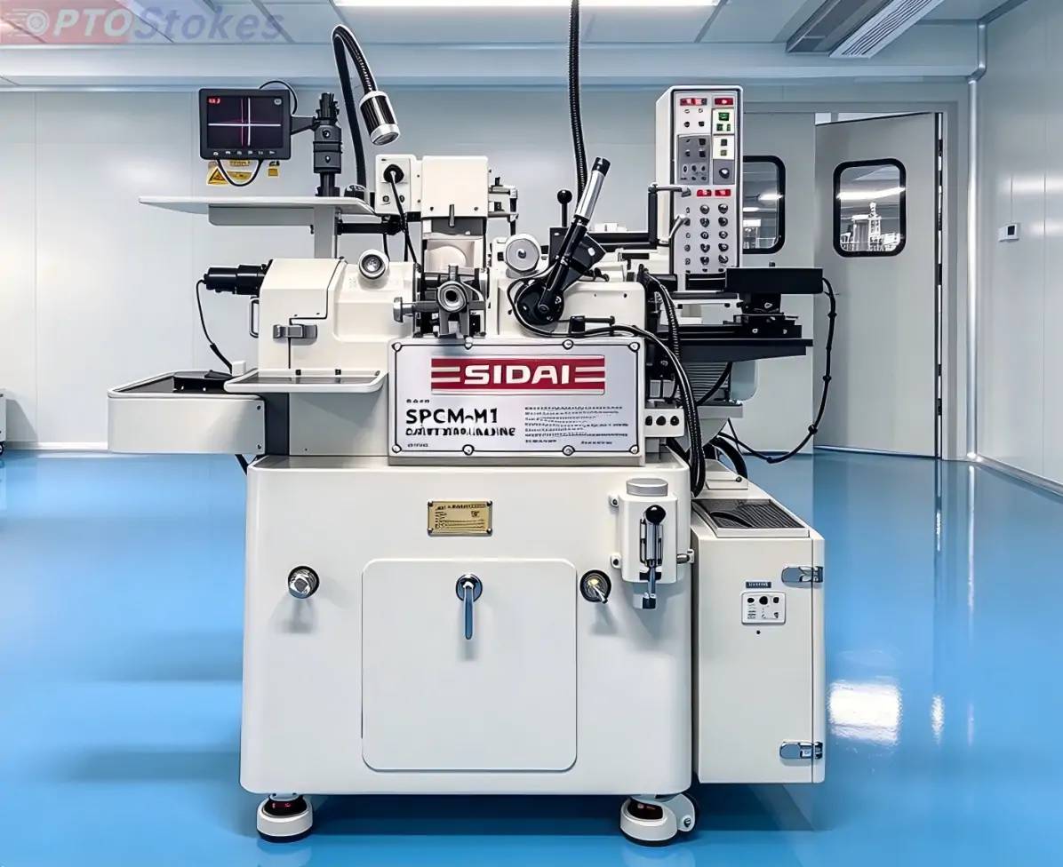
Centering and Edging: The centering step defines the final mechanical axis relative to the optical axis before outer diameter grinding and chamfering. The residual angular deviation left during this step fixes the permanent centration error of the finished optical component.
Centration Methods and Equipment Capabilities
The manufacturing threshold for centration accuracy depends directly on the alignment technology used during the edging process:
| Centering Method | Alignment Mechanism | Residual Centration Level | Suitable Applications |
|---|---|---|---|
| Mechanical Centering (Bell-Clamping) | Self-centering pressure via two concave bell-clamping cups matching lens curvature | Arcminute level (typically ~1′ to 3′) | Commercial-grade singlets, large-diameter optics, low-cost IR windows |
| Optical Centering (Autocollimators) | Direct optical alignment measuring reflected/transmitted spot movement during spindle rotation | Sub-arcsecond to tens of arcseconds (1″–30″) | Precision multi-element lenses, beam expanders, MWIR/LWIR thermal imaging lenses |
Optical Consequences of Centration Error Across IR Materials
1. Optical Windows: Refractive Index Amplification
When a collimated beam passes perpendicularly through a window with wedge angle α, the transmitted beam suffers angular deviation δ defined by Snell's Law (small-angle approximation):
δ = (n − 1) × α
High-refractive-index infrared materials significantly amplify beam deviation compared to visible optical glass (n ≈ 1.5):
| IR Material | Refractive Index (n) at Key Wavelength | Amplification Factor (n − 1) | Beam Deviation (δ) at α = 1′ | Beam Deviation (δ) at α = 30″ |
|---|---|---|---|---|
| Zinc Selenide (ZnSe) | 2.403 (at 10.6 µm) | 1.40 | ≈ 1.4′ (84″) | ≈ 42″ |
| Germanium (Ge) | 4.003 (at 10.6 µm) | 3.00 | ≈ 3.0′ (180″) | ≈ 90″ |
| Silicon (Si) | 3.422 (at 3.4 µm) | 2.42 | ≈ 2.42′ (145″) | ≈ 73″ |
| Chalcogenide Glass (BD-2) | 2.498 (at 10.0 µm) | 1.50 | ≈ 1.5′ (90″) | ≈ 45″ |
For Germanium optics, a 1′ wedge angle introduces 3′ of transmitted beam deviation, causing severe boresight walk-off in interferometric and target designation systems. High-index infrared optics demand strict parallelism controls (1″–30″) due to this inherent physical amplification.
2. Lenses: Focal Spot Displacement and Asymmetric Aberrations
Lens tilt introduces field-independent coma and astigmatism, degrading Modulation Transfer Function (MTF) performance. In high-Numerical-Aperture (NA) focusing lenses (e.g., short focal length CO₂ or thermal lenses with f/1.0 to f/1.2), centration tilt causes severe wave-front asymmetry.
Lateral focal spot shift is approximated by:
Δx ≈ f × θ
A 50.8 mm focal length ZnSe focusing lens with 1′ centration tilt shifts the focal point laterally by ~15 µm. A 3′ tilt shifts the spot by ~45 µm, producing beam trailing and non-uniform kerf widths in laser machining applications.
3. Multi-Element Assemblies: Root-Mean-Square Error Stacking
In multi-element systems such as beam expanders or thermal imaging objectives, individual lens tilts stack statistically rather than cancelling out. System tilt error follows a Root-Mean-Square (RMS) summation:
θ_system = √(θ₁² + θ₂² + ... + θₙ²)
If three singlet lenses with 1′ centration tilt each are combined, system angular residual reaches ~1.7′. To maintain total system deviation within ≤1′, individual lens centration must be toleranced to ≤30″.
Standard Tolerance Classification for Precision IR Optics
| Parameter | Commercial Grade | High-Precision Grade | Application Guidance |
|---|---|---|---|
| Lens Centration (Tilt) | ±1′ | 1″–30″ | Commercial: Singlet focusing, protective windows. High-Precision: Multi-element assemblies, beam expanders, imaging lenses. |
| Window Parallelism | ±1′ | 1″–30″ | Commercial: Debris shields, sight glasses. High-Precision: Interferometry, laser optical paths, thermal imaging windows. |
| Outer Diameter Tolerance | ±0.05 mm | ±0.01 mm | Commercial: Retainer ring / snap fit mounting. High-Precision: Precision barrel mounting (H7 fit). |
| Surface Figure (PV) | 0.5 λ | λ/10 to λ/20 | Matched with centration tier based on system wavefront requirements. |
| Surface Quality (Scratch-Dig) | 60-40 | 10-5 / 20-10 | High-Precision required for high-power CO₂/fiber lasers and sensitive imaging MWIR optics. |
Drawing Callouts and Quality Inspection Protocols
1. Standard References
ISO 10110-6: Specifies centration tolerances and surface tilt tolerances relative to a designated reference axis.
ISO 10110-7 / MIL-PRF-13830B: Governs surface imperfection tolerances (Scratch-Dig).
GB/T 7242-2010: Defines lens centration testing protocols via surface tilt angle χ.
2. Incoming Inspection Procedures
Optical Autocollimation Method: Place lens on a precision air-bearing spindle. Rotate 360° while monitoring reflected crosshair image displacement via autocollimator. Convert image orbit radius to surface tilt angle.
Mechanical Mechanical Measurement (TIR): Mount lens in a precision V-block. Rotate along outer diameter while a high-precision dial indicator measures single-point edge height variation. Calculate single-sided ETV as TIR / 2.
Interferometric Wavefront Analysis: High fringe tilt across the clear aperture under a Fizeau interferometer indicates wedge tilt or optical centration deviation.
Evaluating Supplier Capability for High-Precision IR Optics
To deliver consistent arcsecond-tier centration (1″–30″), an optical manufacturing facility requires two critical operational fundamentals:
Closed-Loop Manufacturing Chain: In-house integration of CNC generating, high-speed polishing, optical centering/edging, vacuum thin-film coating, ultrasonic cleaning, and metrology. Outsourcing edging or coating introduces thermal stress and mechanical re-clamping error, making arcsecond control difficult to maintain.
Metrology-to-Production Ratio: Precision fabrication facilities typically operate a balanced equipment ratio (e.g., ~260 processing units supported by ~65 specialized metrology instruments, approximately 4:1). Without dedicated autocollimators and laser interferometers at edging stations, centration tolerances remain unverified batch-to-batch.
Engineering Evaluation & RFQ Guidelines
When specifying custom IR optical components or requesting a technical evaluation for Chalcogenide glass lenses, Germanium optics, ZnSe focusing lenses, or precision IR windows, specify centration and parallelism callouts explicitly on production drawings:
Singlet / Low-NA systems: Select ±1′ centration grade.
Multi-element / High-NA / Collimated paths: Select 1″–30″ high-precision centration grade with ISO 10110-6 callouts.
For custom engineering review, prototype fabrication, or RFQ support, submit your technical drawings, target optical wavelength (MWIR/LWIR), clear aperture, coating specifications, operating temperature range, and required quantities to OPTOStokes engineering team for an optical manufacturing feasibility assessment.