
ZnSe Plate Beamsplitters
ZnSe plate beamsplitters for CO2 laser beam sampling, splitting, and combining. Review T/R ratio, wavelength, angle, and polarization.
Product Overview
Overview
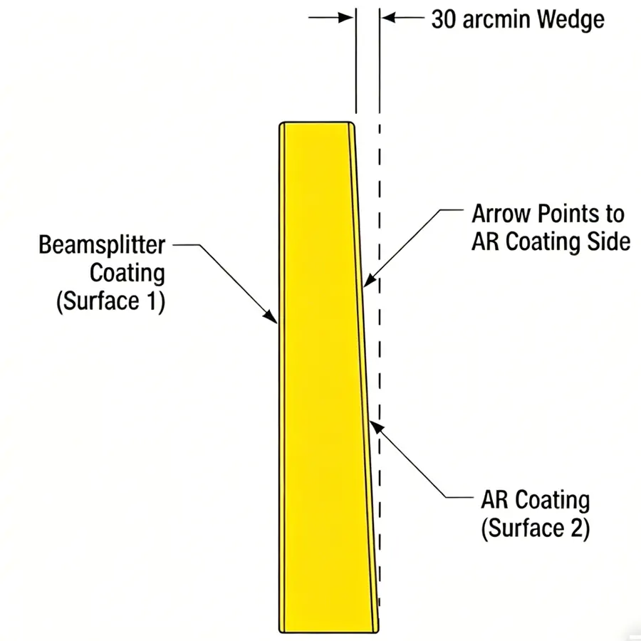
ZnSe plate beamsplitters divide an input infrared beam into transmitted and reflected paths, or combine two beams into one optical path. They are typically specified for CO2 laser optics, IR beam sampling, diagnostics, and beam routing where the coating defines the transmission/reflection ratio.
Why Coating and Polarization Matter
At a typical 45° angle of incidence and 10.6 µm wavelength, s- and p-polarization can respond differently. The final specification should define the target T/R ratio, operating wavelength, angle of incidence, polarization condition, beam size, and coating side before release.
Typical Specifications
| Parameter | Value |
|---|---|
| Material | ZnSe |
| Surface Quality | 60/40 from source note; 40-20 S/D may be reviewed for tighter requirements |
| Diameter Tolerance | +0.0 / -0.1 mm |
| Angle Tolerance | ±3′ (3 arcminutes) |
| Flatness | λ/4, typically at 632.8 nm |
| Size Example | 80×80×1 mm, customizable |
| Coating | AR or beamsplitter coating matched to T/R target |
| Splitting Ratio | 70:30 or custom made |

Engineering Notes
- Confirm whether the optic is used as a beamsplitter, beam sampler, or beam combiner.
- Specify wavelength, angle of incidence, polarization state, and required transmitted/reflected energy balance.
- Share beam diameter, clear aperture, substrate size, coating side, and mechanical mounting limits.
Request Engineering Review
For custom ZnSe beamsplitter coating review, send the wavelength, beam size, angle of incidence, polarization condition, and target T/R ratio through the contact form. You can also compare related ZnSe optics in the product catalog.
Technical Parameters
Detailed specifications are not available for this product yet. Please contact the team for application guidance.