
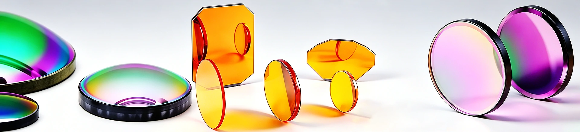
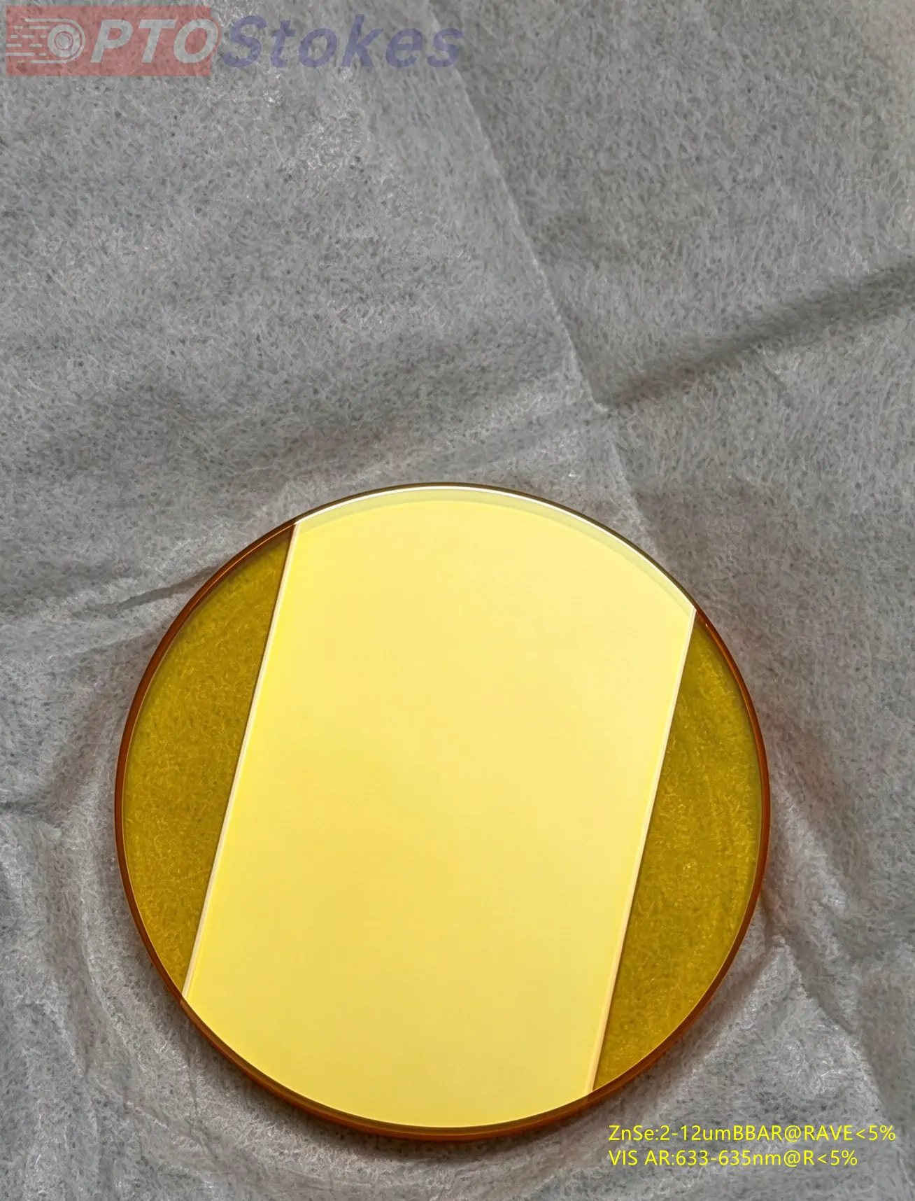
Dual band 50/50 splitting of 2-12 μ m and 633-635nm
CVD zinc selenide beam splitter and compensation plate 32 × 4.0 mm: FTIR interferometer dual band component
CVD zinc selenide (ZnSe) beam splitter and compensation plate, with a diameter of 32 4.0 mm, dual band 50/50 splitting of 2-12 μ m and 633-635nm, used for FTIR interferometer. Customized coating and matching delivery according to drawings
Product Overview
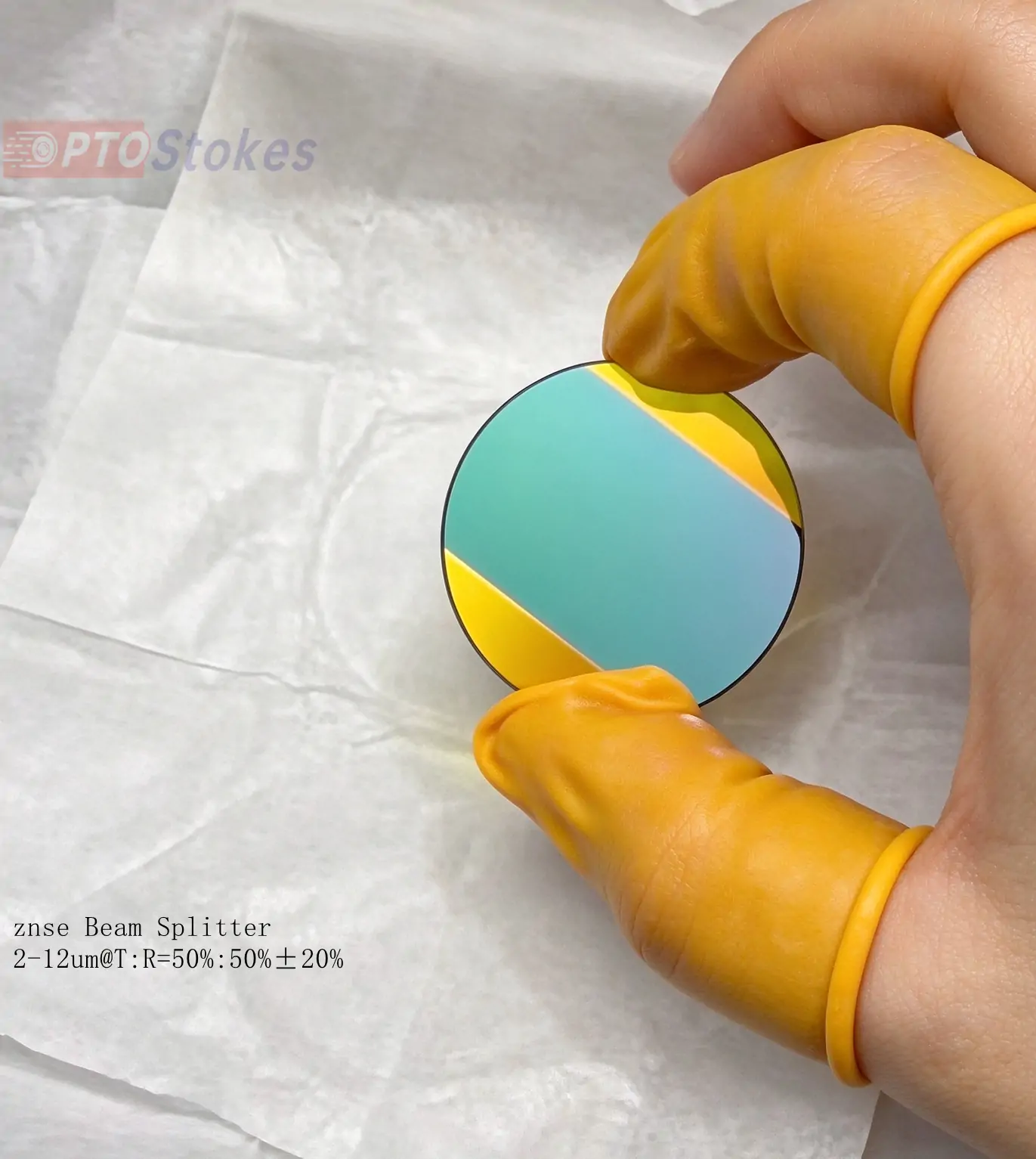
This is a set of beam splitters and compensation plates used for Fourier transform infrared (FTIR) interferometers. The substrate is CVD zinc selenide, with a diameter of 32 mm and a thickness of 4.0 mm. ZnSe is chosen instead of Ge or KBr because it can simultaneously transmit 2-12 μ m infrared and 633-635nm visible light: the latter is a commonly used alignment laser for interferometers. One substrate is used for dual band beam splitting, eliminating the need for a separate visible channel. Although KBr is infrared transparent, it is not visible, and Ge is only transparent from about 1.8 μ m, neither of which can produce this dual band device.
Technical specifications
| Project | Beam splitter (BS) | Compensation plate (CP) |
|---|---|---|
| Substrate/Process | Zinc Selenide (ZnSe), CVD | ZnSe, CVD (homologous pairing with BS) |
| Dimensions | Diameter 32 × 4.0 mm | Diameter 32 × 4.0 mm |
| Infrared performance (2-12 μ m) | Split R/T 50:50 ± 20% | Double sided BBAR, Rave<5% |
| Visible performance (633-635nm) | Beam splitting R/T 50:50 | AR, R< 5% |
| Coating position | Single side beam splitter film | Double side anti reflection film |
| Surface shape/parallelism/surface quality | Confirm according to order | Confirm according to order |
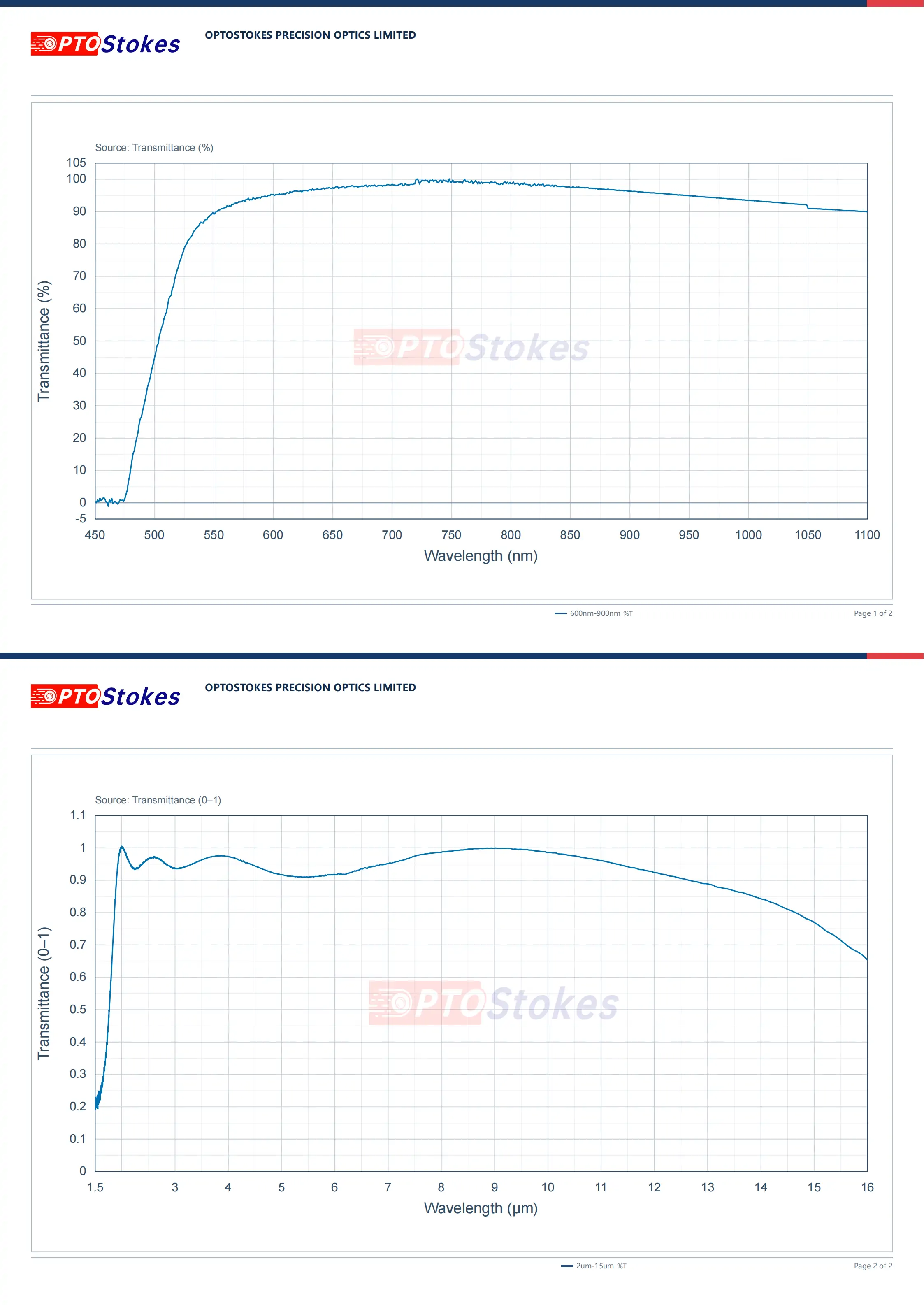
Why do interferometers need a beam splitter with compensating plates? Selection deduction
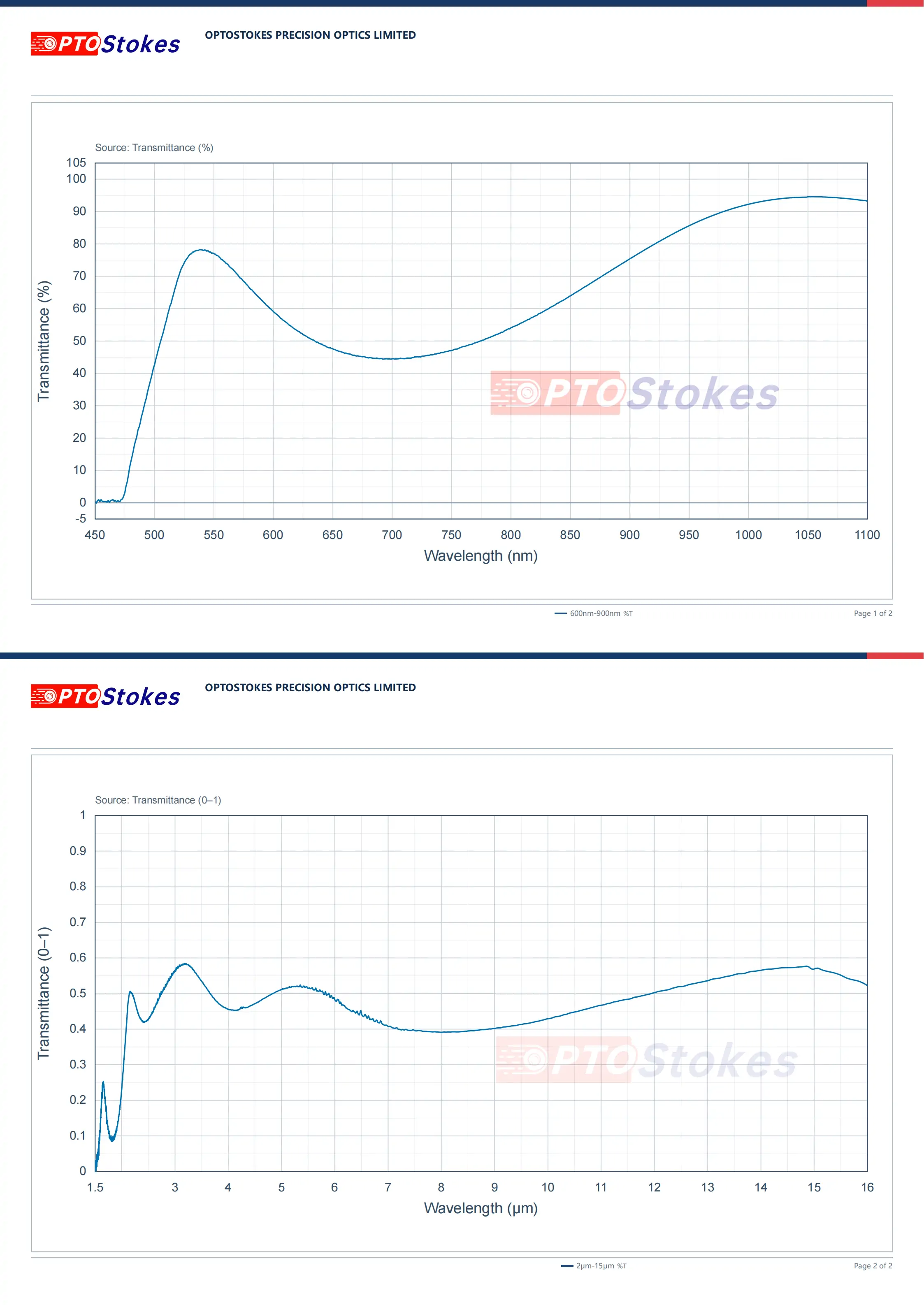
In the Michelson interferometer, the beam splitter divides the light into two paths and then combines them back together; The compensating plate is placed in the reference arm, and its function is not beam splitting, but to compensate for the 4.0 mm ZnSe optical path introduced by the beam splitting mirror substrate - allowing the two arms to travel exactly the same glass thickness except for the beam splitting. Without a compensating plate, or if the two are not of the same source, the optical path length of the two arms is only equal at a certain wavelength. After leaving the center wavelength, dispersion will lower the contrast (visibility) of the stripes, making them more pronounced at the long wavelength end. The trade-off follows: the compensation plate must be double-sided BBAR (2-12 μ m Rave< in this case); 5%、650 nm R< 5%) to avoid dragging down the signal; The beam splitting ratio of 50:50 ± 20% is too loose, and the reflectance within the entire infrared band may fluctuate between 40% and 60%. This wavelength related fluctuation will cause a tilted baseline on the luminous flux curve, and instrument linearity correction is required before quantitative inversion; Therefore, what is required from the manufacturer is the R/T curve with wavelength, rather than a single point value. Applicable boundary: If 633-635 nm is only used for coarse alignment and does not participate in measurement, the beam splitting can be relaxed; If high-resolution is required, BS and CP must be paired and delivered with the same substrate thickness. Verification suggestion written into the protocol: white light interference peak symmetry, BS/CP transmission measured with wavelength, pairing number.
The most frequently overlooked point
Purchase the beam splitter and compensating plate separately as two independent products. According to its function, the compensating plate is the "mirror substitute" of the beam splitter substrate, which must be delivered in pairs with the same origin, thickness, and pairing number; Buying separately and stacking tolerances separately is equivalent to creating optical path mismatch oneself, and the mismatch amount varies with wavelength and is difficult to correct afterwards. The correct approach is to directly request a pair of "beam splitter+compensating plate" when placing an order, and attach the thickness difference and surface shape record of the two.
Customization and Service
The dimensions, single-sided/double-sided coating bands and indicators, surface shape and parallelism tolerances, and matching delivery can all be processed and evaluated according to the drawings. The surface shape and parallelism of the 32mm thin disc have a direct impact on the interference contrast. It is recommended to specify this in the order instead of using the default file. Similar beam splitting/combining components can be found in<a href=“ https://www.iroptical.com/BeamCombiners/ Splitting and Combining Series, see<a ref=for material comparison https://www.iroptical.com/materials/ Infrared Material Page
Information required for inquiry
Requirements for working band and beam splitting ratio, whether dual band (including 633-635 nm alignment) is required, diameter and thickness, surface shape/parallelism, whether to pair and deliver, and quantity. It is faster to attach drawings directly. Sent to sales@iroptical.com , Or through<a ref=“ https://www.iroptical.com/contact/ Inquiry pageSubmit. The specific values for surface shape, parallelism, surface quality, and paired thickness difference are not listed on this page and need to be reviewed and confirmed according to the drawings.