
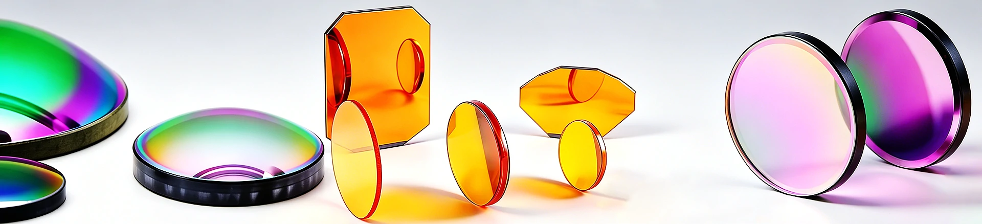
10.6 μ m low absorption, customizable laser window for drilling
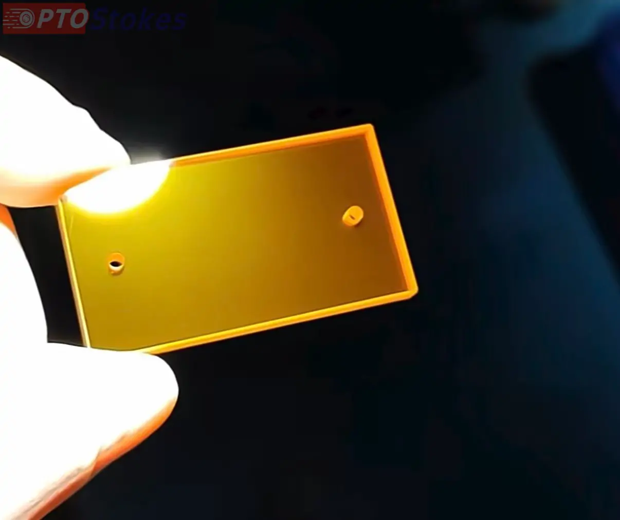
CVD ZnSe drilling optical window 30 × 24 × 2 mm: for CO ₂ laser marking
30 24 2 mm CVD zinc selenide (ZnSe) drilling optical window, surface quality 40/20, low absorption suitable for CO ₂ laser marking optical path. Customizable aperture, coating and irregular processing according to drawings
Product Overview
This is a perforated zinc selenide (ZnSe) optical window for CO ₂ laser marking machines, with an outer shape of 30 × 24 mm, a thickness of 2 mm, and a surface quality of 40/20. It is determined that it is suitable for CO ₂ and not other lasers, based on the fact that ZnSe is only transparent in infrared - visible light and 1064 nm near-infrared are not transparent, and the only CO ₂ optical path that can be used in laser marking is 10.6 μ m. Reason for choosing it: This band has extremely low absorption, high transmittance, and can be drilled for assembly positioning or optical path avoidance. Similar standard components can be found in<a ref=“ https://www.iroptical.com/IRWindows/ Infrared Window Series
Technical specifications
| Project | Parameters | Description |
|---|---|---|
| Materials/Processes | Zinc Selenide (ZnSe), CVD | Optical grade Polycrystalline |
| Dimensions | 30 × 24 mm | Rectangular |
| Thickness | 2 mm | Thin parts with limited rigidity |
| Surface Quality | 40/20 (scratch dig) | Enter Given Value |
| Hole position/diameter/number | Confirm according to the drawing | Drilled, not specified |
| Coating | Confirm according to order | Usually required AR@10.6 μm |
| Surface shape/parallelism | Confirm according to order | Not given |
| Refractive index/absorption | n ≈ 2.4@10.6 μm; Typical absorption coefficient<0.0005 cm ⁻¹ | Material typical value |
Why use ZnSe window for marking optical path: selection deduction
Set up a CO ₂ marking machine with an optical path of laser tube → beam expander → galvanometer → focusing lens, and a protective window in front of the focusing lens to prevent material splashing. The window does not directly bear the focusing energy, but there is still a considerable power density at 10.6 μ m round-trip, so low absorption materials must be used, and ZnSe is the standard choice here; If replaced with Ge, although it also penetrates 10.6 μ m, the absorption and thermal load margin are tighter and heavier. Choice point: The window should be coated with at least 10.6 μ m anti reflection, otherwise about 17% of the reflection on both sides will not only lose power, but also form ghost images inside the cavity or between the mirror groups, burning adjacent lenses; If the hole is used for assembly, the edge stress and burrs of the hole will damage the local surface shape. Applicable boundary: If the window is located near the focused spot or experiences reflected light, it should be inspected according to the lens level damage threshold rather than the window level. Write verification suggestions into the protocol -10.6 μ m transmission curve after plating, 50 × microscopic inspection of hole edges, high-power aging pilot.
The purpose of drilling determines the acceptance diameter
Before placing an order, distinguish whether the hole is used for assembly or for lighting. Assembly holes only require accurate positioning, no broken edges, and no light leakage; The edge of the aperture (diaphragm type window) is the boundary of the light beam, and burrs and diffraction will directly degrade the spot. Acceptance should be based on the quality inspection of the aperture edge, rather than just looking at "aperture through". The process and inspection of the two are completely different. The function, aperture tolerance, and positional accuracy of the holes must be marked on the drawings. Otherwise, the manufacturer can only follow the looser assembly hole standard, which may cause problems with the optical components.
Three hidden diseases of drilling ZnSe
The first is edge collapse and microcracks. The Knoop hardness of ZnSe is only about 105 kg/mm ², which is softer than common optical glass. It is also a polycrystalline brittle material. When drilling on a 2mm thin piece, the exit side is prone to edge breakage, leaving micro cracks on the hole wall that are difficult to distinguish with the naked eye. These cracks will become local hotspots at a high power of 10.6 μ m - light is scattered and absorbed by the cracks, the temperature rises first, then the cracks propagate, the film layer peels off, and ultimately the entire piece fails. The correct approach is to chamfer before cutting, control the drilling speed, and conduct a full inspection of the hole edge with a microscope of 50 × or more. After coating, re inspect the hole circumference again, rather than just checking if the hole is through.
The second is to consider 40/20 as a high-power safety line. 40/20 is sufficient for general windows, but scratches at 10.6 μ m will amplify into scattering sources, and the power density at densely scratched areas will increase, which may cause damage before the design threshold. If the marking machine is running at full power or the window is facing the reflected light, it is recommended to increase the surface quality to 20/10 or 10/5 and confirm with the manufacturer, instead of using the default value of 40/20.
The third is to install a hard press ring. ZnSe soft and 2mm thin parts have poor rigidity, and direct pre tightening of metal pressure ring screws can cause local deformation or even fragmentation, resulting in damage to the surface shape of the illuminated area and a decrease in the quality of the marking spot. The correct approach is to use elastic washers to press the surface, apply uniform torque, avoid point contact, and interfere with the surface shape after installation.
Customization and Service
Circular, square, irregular windows and perforated parts are all processed according to the drawings; The drilling position, aperture, chamfer, coating band and indicators, surface shape and parallelism can be customized and evaluated. The drilling and deformation control of ZnSe soft materials are our process focus. Material comparison can be found in<a ref=“ https://www.iroptical.com/materials/ Infrared Material Page
Information required for inquiry
The working wavelength (usually 10.6 μ m CO ₂), shape and thickness, hole layout and aperture number, surface quality, coating requirements and quantity, please refer to the attached drawings as soon as possible. Sent to sales@iroptical.com , Or through<a ref=“ https://www.iroptical.com/contact/ Inquiry pageSubmit. The specific values for hole position, coating, surface shape, and parallelism are not listed on this page and need to be reviewed and confirmed according to the drawings.